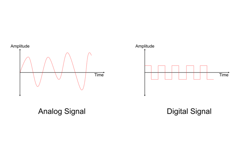
Digital Circuits

RLC Circuit Phasor Sine Wave and Animation Analysis

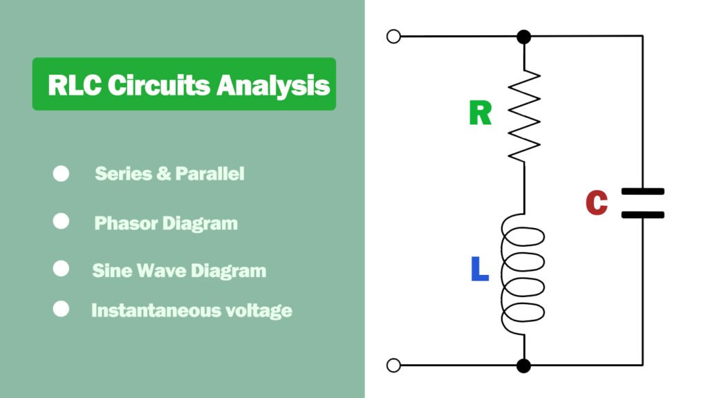
RLC Circuit – Phasor, Sine Wave, and Animation Analysis

What is an RLC circuit? An RLC circuit is an electrical circuit that contains a resistor (R), inductor (L), and capacitor (C) connected in series or parallel. These components work together to store and transfer energy, leading to oscillations at a specific resonant frequency. RLC circuits are commonly used in various applications, including filters, oscillators, […]

RLC Circuit – Phasor, Sine Wave, and Animation Analysis Read More »

NOR Gate Symbol

NOR Gate Simplifying Boolean Expression

Introduction to Boolean expressions Boolean expressions are fundamental components of digital logic design. They represent logical relationships between variables, typically resulting in a binary output. These expressions are crucial for building efficient and reliable digital circuits. In this article, we will delve into the world of Boolean expressions and focus on one specific gate: the

NOR Gate Simplifying Boolean Expression Read More »

Logic Gates

Logic Gates: Tyles, Symbol, Truth Table

Logic Gates are the basic components on Integrated Circuits. Simple logic gates can be made of transistors. The combination of these transistors can make the high and low levels representing the two signals pass through them to generate a high or low level signal. High and low levels can respectively represent logical “true” and “false”

Logic Gates: Tyles, Symbol, Truth Table Read More »

Transistor-Transistor Logic (TTL)

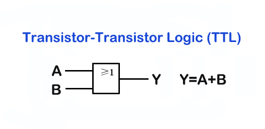
TTL Logic: What is and How Does it Work?

What is TTL? TTL, or Transistor-Transistor Logic, is a type of digital circuit design that uses bipolar transistor technology to create logic gates. TTL is commonly used in electronics, particularly in the design of digital circuits, because it is fast and reliable. It is also relatively easy to understand and design with TTL logic, making

TTL Logic: What is and How Does it Work? Read More »

Voltage Controlled Voltage Sources (VCVS)

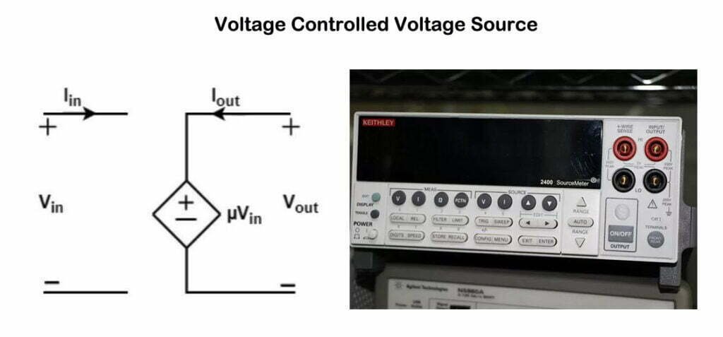
Understanding Voltage Controlled Voltage Sources (VCVS)

Voltage Controlled Voltage Sources (VCVS) are a fundamental and essential part of electronic circuit design and analysis. In this article, we will discuss the basics of VCVS, its applications, and its role in the broader context of electronic components. Introduction to VCVS A Voltage Controlled Voltage Source (VCVS) is a type of dependent source that

Understanding Voltage Controlled Voltage Sources (VCVS) Read More »

Scroll to Top
welldone pcb manufacturer

Start to Achieve Your PCB Project

Our office will be closed from Jan 21st to Feb 5th, 2025 for the Chinese New Year holiday. Orders and inquiries will be processed after holiday.

Open chat
Scan the code
Hello 👋
Can we help you? Chat with us on WhatsApp↓, or send an email to us: info@reversepcb.com