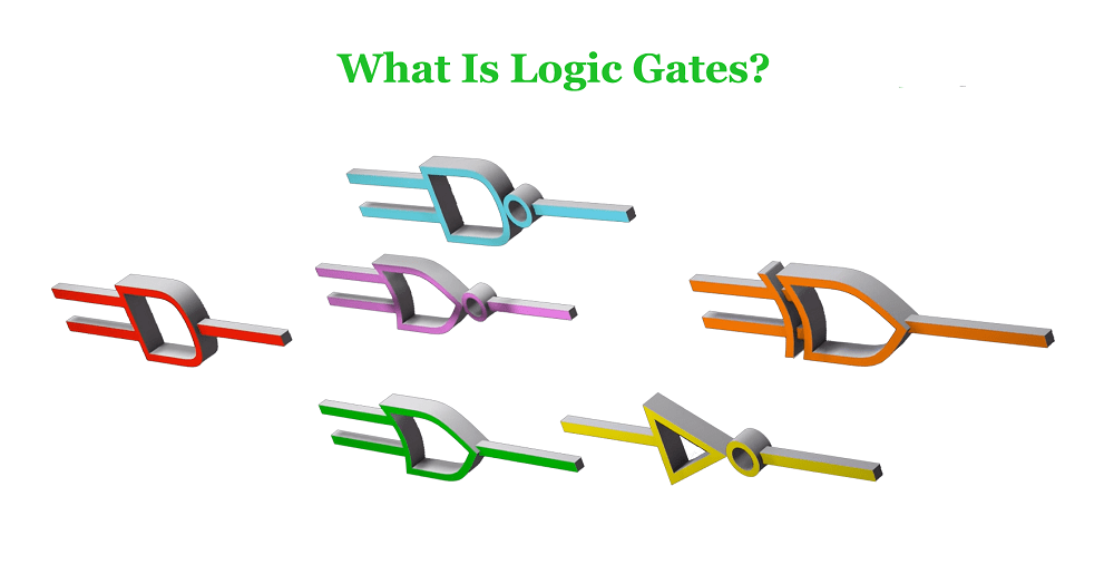
Logic Gates are the basic components on Integrated Circuits. Simple logic gates can be made of transistors. The combination of these transistors can make the high and low levels representing the two signals pass through them to generate a high or low level signal. High and low levels can respectively represent logical “true” and “false” or 1 and 0 in binary, thereby realizing logic operations. To delve deeper into one of these foundational components, learn about PMOS transistors.
Basic Logic Gates
Here we will introduce 7 basic logic gates: AND gate, OR gate, NOT gate, NAND gate, NOR gate, XOR gate and XNOR gate. You‘ll learn their logical symbols, logical relations and truth tables.
AND Gate
AND gate is also called “AND circuit”, logic “AND” circuit. It is a basic logic gate circuit that performs “AND” operation. There are multiple inputs and one output.
The output is high when all inputs are high (logic 1) at the same time, otherwise the output is low (logic 0).
The mathematical logic expression of AND gate: Y = AB, the truth table is as follows:

| Input | Output | |
|---|---|---|
| A | B | Y |
| 0 | 0 | 0 |
| 0 | 1 | 0 |
| 1 | 0 | 0 |
| 1 | 1 | 1 |
OR Gate
OR gate, also known as OR circuit, logic and circuit. If one of several conditions is met, an event will occur. This relationship is called an “or” logical relationship. A circuit with an “OR” logic relationship is called an OR gate.
The OR gate has multiple inputs and one output, as long as one of the inputs is high (logic “1”), the output is high (logic “1”). The output is low (logic “0”) only when all inputs are low (logic “0”).
The mathematical logic expression of the OR gate is: Y=A+B=(A’B’)’, and its logical symbols and truth table are as follows:

| Input | Output | |
|---|---|---|
| A | B | Y |
| 0 | 0 | 0 |
| 0 | 1 | 1 |
| 1 | 0 | 1 |
| 1 | 1 | 1 |
NOT Gate
A NOT gate, also known as a NOT circuit, an inverter, or a logic negation circuit, is the basic unit of a logic circuit. A NOT gate has one input and one output.
When the input is high (logic “1”), the output is low (logic “0”); conversely, when the input is low (logic “0”), the output is high level (logic “1”). The logic function of the NOT gate is equivalent to the NOT in the logic algebra, and the circuit function is equivalent to the inversion. This operation is also called the NOT operation.
The mathematical logic expression of the NOT gate is: F=A , and its logical symbols and truth table are as follows:

| Input | Output |
|---|---|
| A | Y |
| 0 | 1 |
| 1 | 0 |
NAND Gate
NAND gate is a basic logic circuit of digital circuit. It is a superposition of AND and NOT gates, with multiple inputs and one output.
The AND operation is performed first, followed by the NOT operation. When both inputs are high (1), the output is low (0); if at least one of the inputs is low (0), the output is high (1).
The logic symbol and truth table of the NAND gate are as follows:

| Input | Output | |
|---|---|---|
| A | B | Y |
| 0 | 0 | 1 |
| 0 | 1 | 1 |
| 1 | 0 | 1 |
| 1 | 1 | 0 |
NOR Gate
The NOR gate is the basic element in the digital logic circuit, which realizes the logical OR function. It has multiple inputs, 1 output, and the multi-input NOR gate can be composed of 2-input NOR gate and inverter.
The output is high (logic 1) when both inputs A and B are low (logic 0). When any input is high (logic 1), the output is low (logic 0).
The mathematical expression of its logical relationship is: Y=A+B, the logical symbol and truth table of the NOR gate are shown in the table below.

| Input | Output | |
|---|---|---|
| A | B | Y |
| 0 | 0 | 1 |
| 0 | 1 | 0 |
| 1 | 0 | 0 |
| 1 | 1 | 0 |
XOR Gate
An XOR gate is a logic gate that implements a logical XOR in digital logic. There are multiple inputs and one output, and the multi-input XOR gate can be composed of two-input XOR gates.
If the levels of the two inputs are different, the output is a high level 1; if the levels of the two inputs are the same, the output is a low level 0. That is, if the two inputs are different, the XOR gate outputs a high level 1.
The logical expression of the XOR gate: Y=A⊕B=A•B’+A’•B, the logical symbol and truth table of the XOR gate are as follows:

| Input | Output | |
|---|---|---|
| A | B | Y |
| 0 | 0 | 0 |
| 0 | 1 | 1 |
| 1 | 0 | 1 |
| 1 | 1 | 0 |
XNOR Gate
XNOR gate, also called equivalence gate, is the basic unit of digital logic circuit. It is formed by adding a NOT gate to the output of the XOR gate, and has 2 input terminals and 1 output terminal.
When one and only one of the two inputs is low (logic 0), the output is low. When the levels at the 2 inputs are the same, the output is high (logic 1).
Logical expression: F=A⊙B=A•B+A’•B’=(AB)’, the logic symbol and truth table of XNOR gate are as follows:

| Input | Output | |
|---|---|---|
| A | B | Y |
| 0 | 0 | 1 |
| 0 | 1 | 0 |
| 1 | 0 | 0 |
| 1 | 1 | 1 |
Practical Notes for logic gates
For engineers researching logic gates, the most useful next step is to connect the concept to board-level constraints instead of treating it as an isolated definition. In a real PCB review, confirm the electrical limits, layout dependencies, measurement method, and failure symptoms before changing components or firmware.
- Design context: Review truth tables, CMOS/TTL families, fan-out, propagation delay, and board-level debugging.
- Board inspection: Check component markings, connector orientation, reference designators, supply rails, and nearby protection components before making conclusions.
- Measurement plan: Use a current-limited supply first, then verify continuity, voltage rails, clock/reset behavior, and relevant signal waveforms.
- Documentation: Record photos, measured values, part numbers, and test conditions so later PCB reverse engineering or repair work can be repeated safely.
This checklist helps connect the search intent behind logic gates with practical electronics troubleshooting, PCB design review, and reverse engineering decisions.