Voltage Controlled Voltage Sources (VCVS) are a fundamental and essential part of electronic circuit design and analysis. In this article, we will discuss the basics of VCVS, its applications, and its role in the broader context of electronic components.
Introduction to VCVS
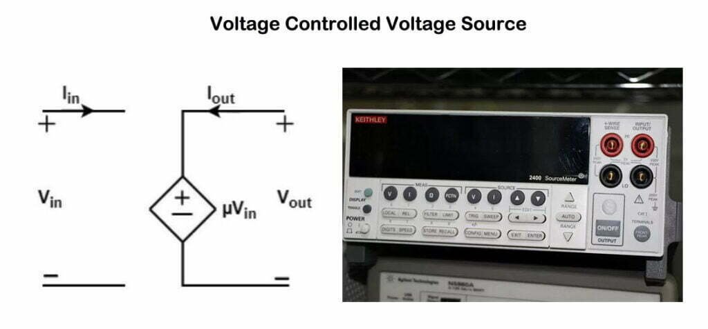
A Voltage Controlled Voltage Source (VCVS) is a type of dependent source that generates a voltage output proportional to a voltage input elsewhere in the circuit. The output voltage is typically represented as:
V_out = A * V_in
Where V_out is the output voltage, A is the gain factor, and V_in is the input voltage. VCVS are widely used in electronic circuit design for applications such as amplifiers, signal processing, and power regulation.
Basics of Dependent Sources
Dependent sources are electronic components that produce outputs based on the values of other circuit elements. They are used for modeling and analyzing more complex components like transistors and operational amplifiers. There are four primary types of dependent sources:
- Voltage Controlled Voltage Source (VCVS)
- Current Controlled Voltage Source (CCVS)
- Voltage Controlled Current Source (VCCS)
- Current Controlled Current Source (CCCS)
Each of these sources has a unique relationship between its input and output, which allows for greater flexibility in designing and analyzing electronic circuits.
 1")
1. Voltage Controlled Voltage Source (VCVS)
Voltage control voltage source, as shown in Figure 1, the voltage of the controlled voltage source is: u2=μu1, where μ is a dimensionless voltage control coefficient. For example, the transformer output voltage is controlled by the input voltage.
 2")
2. Current Controlled Voltage Source (CCVS)
Current control voltage source, as shown in Figure 2, the voltage of the controlled voltage source is: u2=ri1, where r is the current control coefficient, the unit is Ω (ohm), and r is called the transfer resistance.
 3")
3. Voltage Controlled Current Source (VCCS)
Voltage control current source, as shown in Figure 3, the current of the controlled current source is: i2=gu1, where g is the voltage control coefficient, the unit is S (Siemens), and g is called transfer conductance.
 4")
4. Current Controlled Current Sources (CCCS)
Current control current source, as shown in Figure 4, the current of the controlled current source is: i2=βi1, where β is the dimensionless current control coefficient or current gain. For example, the collector current of a transistor is controlled by the base current.
 5")
VCVS in Electronic Circuit Design
Amplifiers
One of the most common applications of VCVS is in the design of amplifiers. Amplifiers are electronic devices that increase the amplitude of a signal without altering its shape. In an amplifier circuit, a VCVS can be used to model the behavior of an ideal operational amplifier (op-amp). The gain factor A represents the amplification factor of the op-amp, which can be controlled to achieve the desired output voltage.
Signal Processing
VCVS also play a significant role in signal processing. They can be used to design filters, which are essential components of many electronic systems. Filters are used to remove unwanted frequencies from a signal while preserving the desired frequencies. By using a VCVS in conjunction with other electronic components, such as resistors and capacitors, a variety of filter designs can be created to suit specific applications.
Power Regulation
VCVS can also be used in power regulation circuits, such as linear voltage regulators. These devices provide a stable and constant output voltage, regardless of variations in input voltage or load current. The VCVS serves as a crucial component in the feedback loop of the regulator circuit, ensuring that the output voltage remains constant even as the input voltage or load conditions change.
Analyzing Circuits with VCVS
In order to analyze circuits containing VCVS, it is essential to understand the underlying equations and principles governing their behavior. The following sections provide an overview of the key concepts and techniques needed to analyze VCVS circuits effectively.
Kirchhoff's Laws and VCVS
An essential tool for analyzing circuits with VCVS is Kirchhoff’s Laws. These laws, consisting of Kirchhoff’s Voltage Law (KVL) and Kirchhoff’s Current Law (KCL), help establish the relationships between voltages and currents in a circuit. For circuits containing VCVS, KVL and KCL can be applied to derive the necessary equations to determine the behavior of the circuit.
Linear Systems and VCVS
Since VCVS are linear dependent sources, they can be analyzed using techniques from linear systems theory. By expressing the circuit equations in matrix form, various methods such as Gaussian elimination, Cramer’s rule, or matrix inversion can be used to solve for the unknown node voltages or currents. This approach simplifies the analysis process and provides a systematic method for solving more complex circuits involving VCVS.
Simulation Tools for VCVS Circuits
There are various simulation tools available for analyzing and designing circuits with VCVS. Software packages like SPICE, LTspice, and CircuitLab allow users to create and simulate electronic circuits containing VCVS and other components. These tools provide valuable insights into the behavior of the circuits and can help identify potential issues or areas for improvement.
Advanced Applications of VCVS
Modeling Complex Components
VCVS can be used to model more complex components, such as transistors, in electronic circuits. By representing the behavior of these components as a VCVS, the analysis and design process can be simplified significantly. This approach allows for more accurate and efficient modeling of the circuit’s overall performance.
Feedback and Control Systems
VCVS is also used in feedback and control systems. These systems rely on the ability to sense and adjust the output of a circuit based on a reference value. By using a VCVS as part of the feedback loop, the system can be designed to maintain a desired output voltage or current, despite variations in the input or load conditions.
Engineering checks for voltage controlled voltage source models
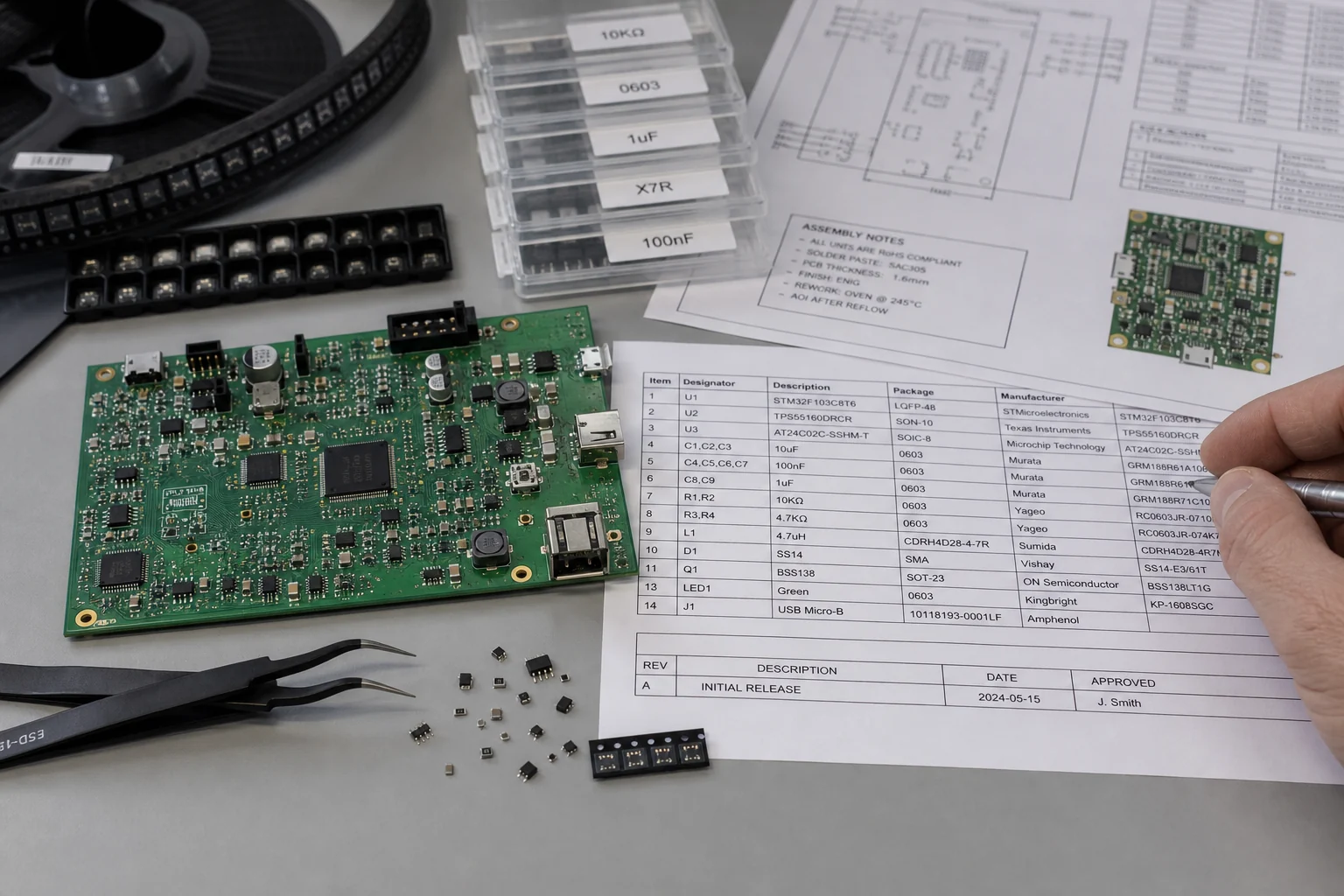
Before using voltage controlled voltage source models in a PCB, firmware, repair, or validation workflow, confirm the details that usually decide whether the design works reliably instead of only reading the headline specification.
Design and troubleshooting checklist
| Area | What to check | Why it matters |
|---|---|---|
| Transfer function | Define gain, input polarity, output compliance, and reference node before drawing the VCVS symbol | A wrong sign or ground reference changes the behavior of the entire circuit model |
| Simulation limits | Add realistic bandwidth, output resistance, saturation, and slew-rate assumptions where needed | Ideal dependent sources can hide stability and loading problems in SPICE simulations |
| Circuit use | Apply VCVS blocks to op-amp macro models, sensor interfaces, filters, and controlled feedback loops | The model is useful only when its assumptions match the real PCB circuit |
These checks help connect the search intent around voltage controlled voltage source with practical board-level decisions, component selection, and failure analysis.
Conclusion
Voltage Controlled Voltage Sources (VCVS) are an essential component in electronic circuit design and analysis. Their versatile nature allows for a wide range of applications, from amplifiers to signal processing and power regulation. Understanding the principles governing VCVS and the techniques for analyzing circuits containing them is crucial for effective circuit design and optimization.