What is Keil μVision5?
Keil µVision is the Windows-only desktop IDE and debugger included with Arm Keil MDK for Arm microcontroller development. It manages projects, builds, packs, flash programming and debug sessions; the compiler, device pack and debug adapter remain separate choices. Arm now presents µVision alongside the newer cross-platform Keil Studio in MDK v6. Arm Keil MDK.
Keil Related Terms
IDE
Integrated Development Environment, which means development integrated environment, generally includes tools such as code editor, compiler, debugger and graphical user interface.
Keil
Keil is Arm’s embedded-development tool brand. Current Keil MDK v6 combines Keil Studio, the proven µVision IDE, compilers, CMSIS tooling, device packs, middleware and debug support; those are components and editions, not interchangeable µVision versions.
uVision
µVision5 is the proven Windows IDE retained in the current MDK product. It should not be described as Arm’s newest IDE: Keil Studio is the newer cross-platform IDE, while µVision remains important for established Windows projects and Pack Installer workflows.
MDK、C51
For Cortex-M projects, select the suitable Keil MDK edition and supported toolchain/device pack. Legacy 8051 projects use the C51 toolchain; C51 and MDK are product/toolchain families, not two editions of the same IDE. MDK Community is free for non-commercial work; commercial use requires the applicable Essential or Professional license. MDK Community licensing.
CMSIS
ARM Cortex™ Microcontroller Software Interface Standard (CMSIS: Cortex Microcontroller Software Interface Standard) is a vendor-neutral hardware abstraction layer for the Cortex-M processor family.
Keil µVision5 Project Setup from Device Pack to Debug Session
A reproducible keil µvision5 project binds the selected device, software pack, compiler, startup code, system clock, linker regions, and debugger settings to one documented configuration. Create a minimal target first, confirm the generated memory map and reset path, and only then add middleware or application modules.
- Select the device: install and record the exact device pack and choose the full ordering code where available.
- Define the target: set oscillator value, memory areas, preprocessor symbols, optimization, warnings, and output artifacts.
- Review startup: verify vector table, stack and heap sizes, clock initialization, and entry into
main. - Configure debug: choose the physical probe, interface, clock, reset strategy, flash algorithm, and trace capability.
- Know simulation limits: confirm which core and peripheral behaviors are modeled, then validate timing and electrical interactions on hardware.
How to Use Keil μVision5?
Step 1: Download and Install Keil5
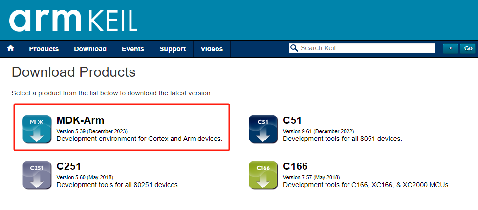
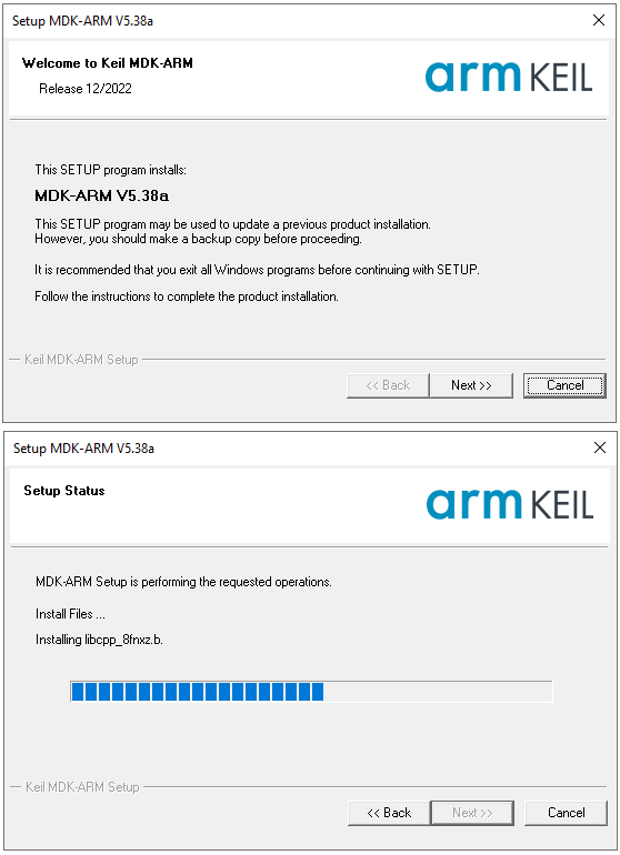
Use the official Arm Keil MDK page to choose the current edition, host platform and license. For µVision, confirm Windows support, activate the appropriate license, then install the exact CMSIS device pack before creating the target. Official Keil support and documentation.
Step 2: Installing Device Packs
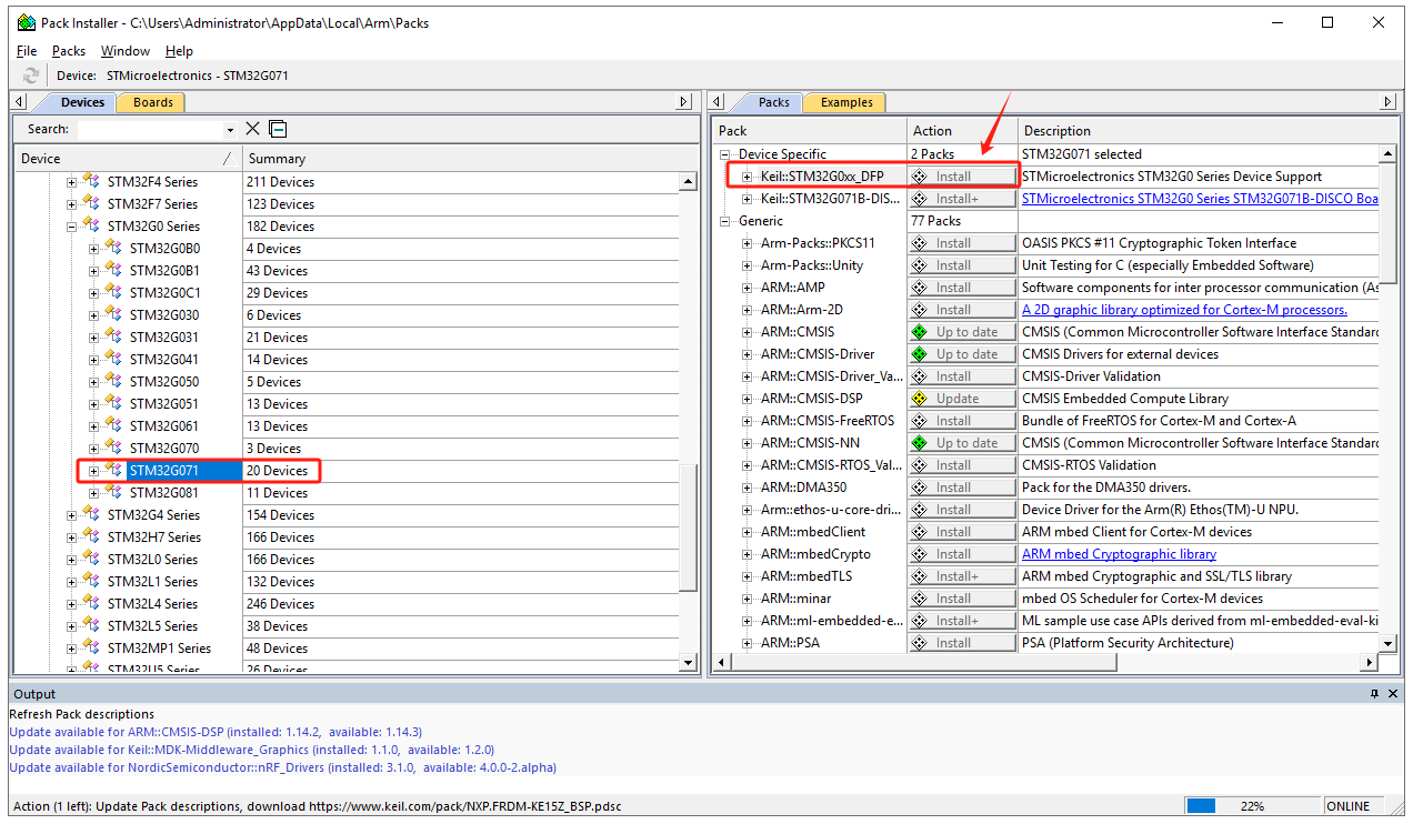
In Keil, click on “Pack Installer” to automatically update information on all device packs from the official website. After the update, select the desired chip model, e.g., STM32G071, and in the right window, find “Device Specific” -> “Keil:STM32G0xx_DFP” and click “Install” to download and install. Once completed, the “Install” button will change to “up to date,” indicating successful installation.
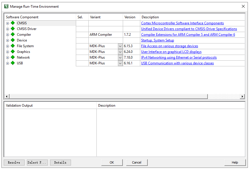
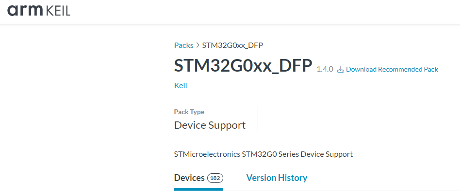
If unable to install from Keil, download the required device pack from the Keil official website:
https://www.keil.arm.com/packs/stm32g0xx_dfp-keil/devices/
Step 3: Creating a New Project
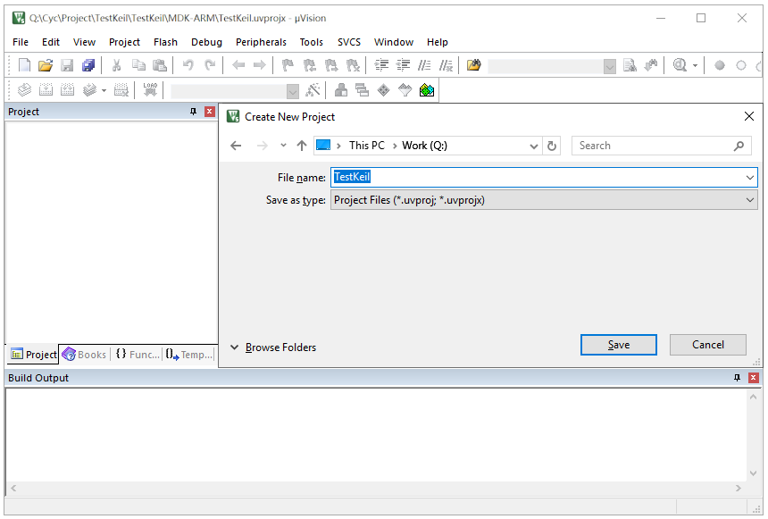
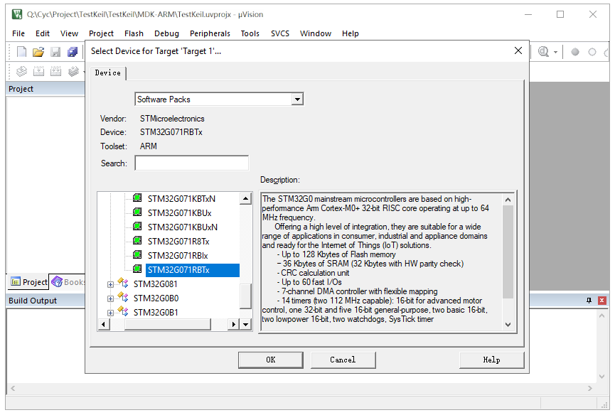
Click on “Project” -> “New Project” to create a new project. Choose the project’s save path and set the project name. The software will prompt for the MCU model; select STM32G071RBTx and choose the CMSIS interface standard.
Step 4: Adding/Creating Files
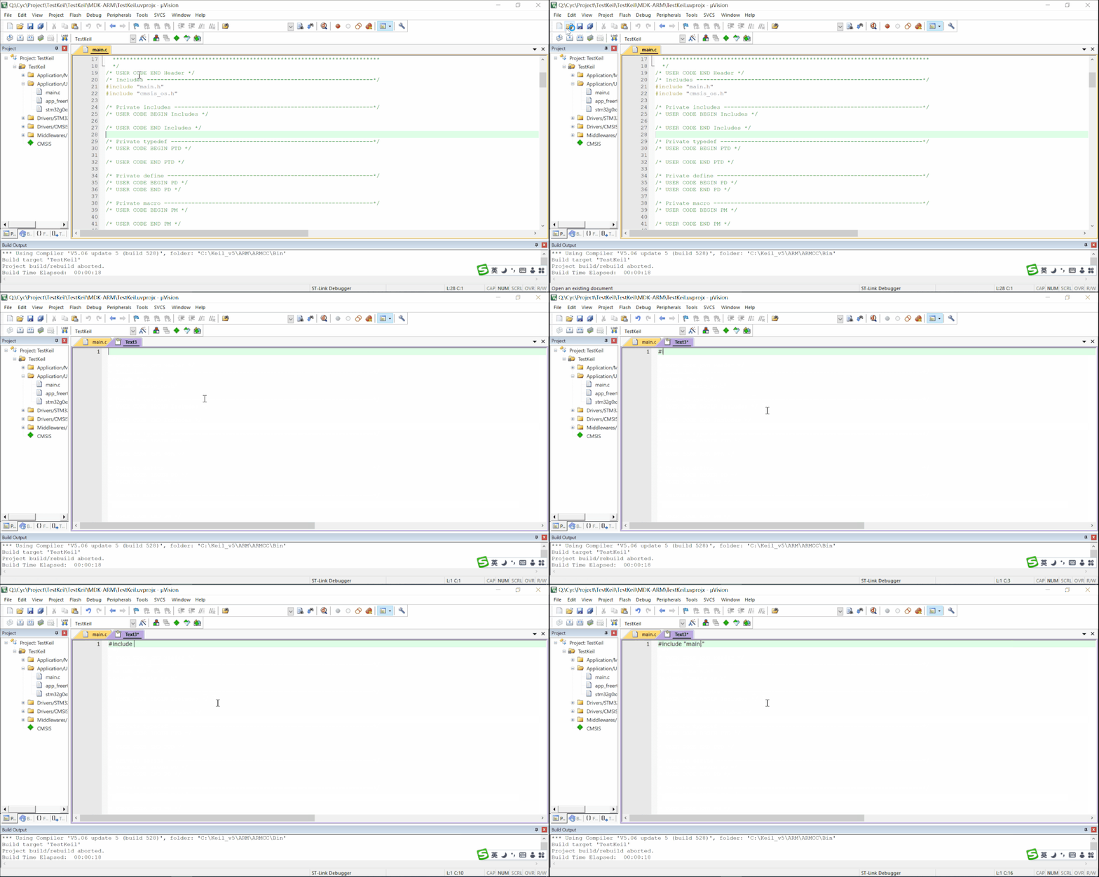
Add necessary code files such as “main.c,” rules for LED blinking, and driver files to the project folder.
Step 5: Project Configuration
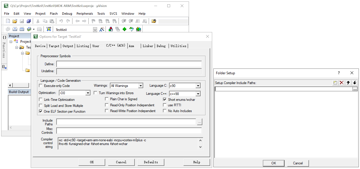
Include header file paths manually for the core code files.
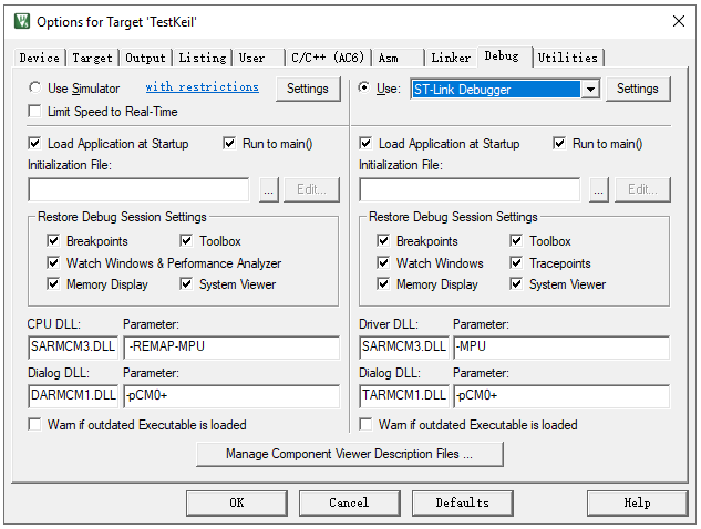
Select the debugger type, e.g., ST-Link, for online debugging.
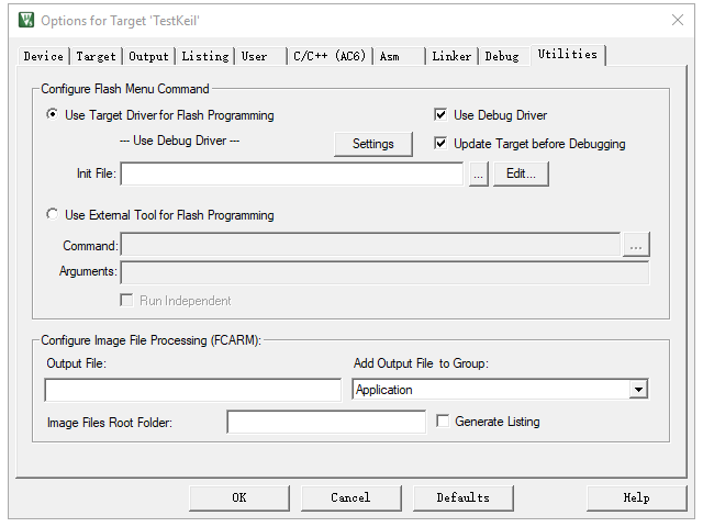
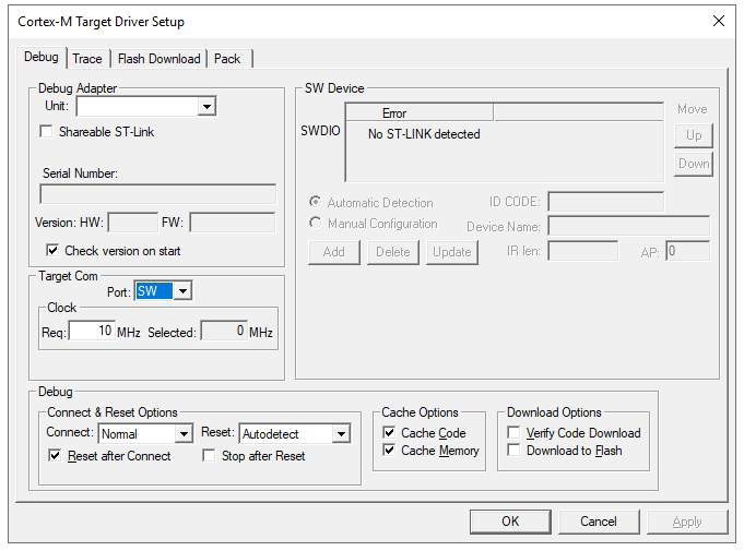
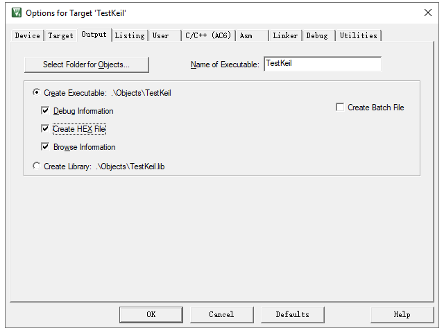
Choose “Create HEX File” to generate a Hex executable file.
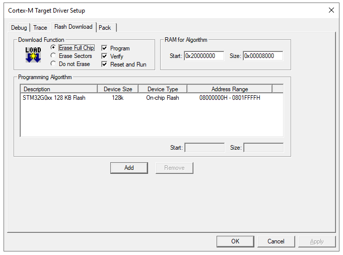
Select “Reset and Run” to run the program immediately after programming.
Step 6: Compilation
After adding files and configuring the project, click on compile. The software will invoke the compiler and linker to convert the source code (.c, .h files) into a machine-readable .axf file containing binary machine code and debugging information.
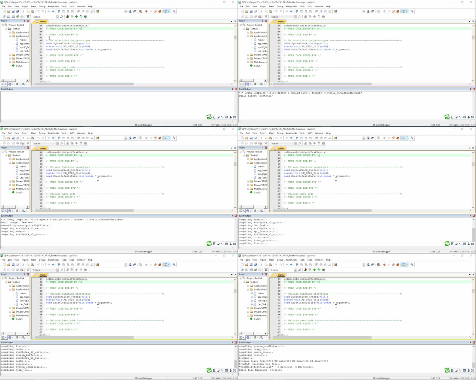
Note: Resolve any error messages before successfully generating the executable file. Warning messages can be addressed based on the situation.
Step 7: Programming
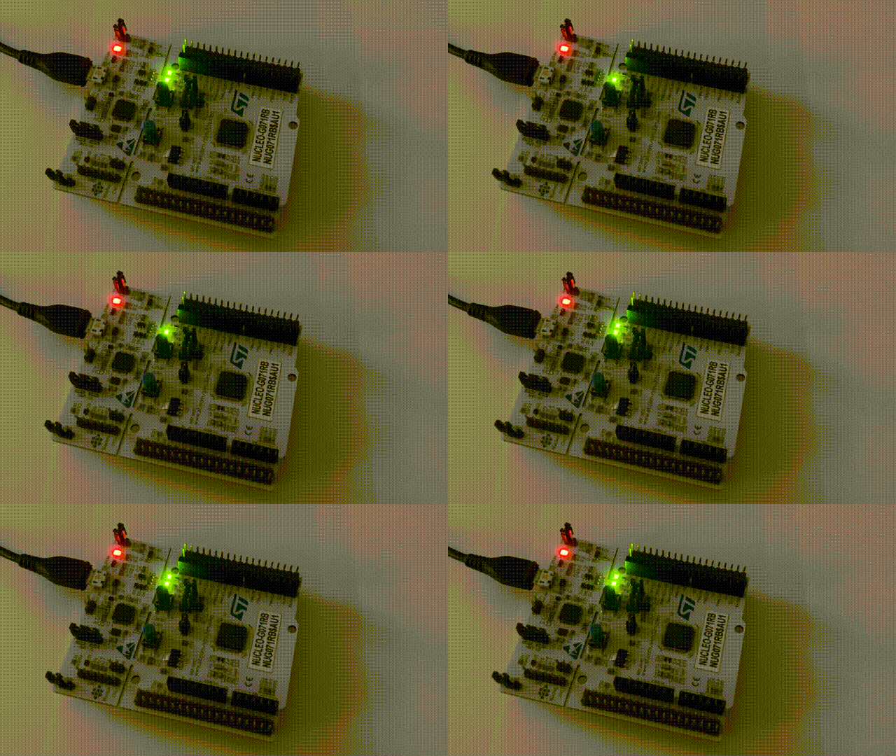
Connect the supported debug adapter, power the target, and verify Project > Options for Target > Debug > Settings. Configure the matching Flash Download algorithm, then use Flash > Download (or the toolbar Download command) to program the image; review the Build Output for erase, program and verify results.

A blinking LED is only a smoke test. Confirm the build/programming log, reset behavior, clock, expected GPIO timing and any required peripherals before treating the image as validated.
Step 8: Debugging
Online Debugging: With a development board, burn the software into the microcontroller and use the debugger to monitor the running program in real-time. Keil provides a user-friendly interface for quick issue identification.
Offline Simulation: Without a development board, use offline simulation to roughly test the logic. However, this method is not suitable if the logic involves peripherals or external circuitry.