An oscilloscope is an essential tool for electrical engineers and hobbyists alike. It’s a powerful diagnostic device that can help you measure, visualize, and analyze waveforms, allowing you to quickly troubleshoot and debug your electronics projects. In this blog post, we’ll uncover the basics of how to use an oscilloscope, including parts of an oscilloscope, connecting and setting up an oscilloscope, using the oscilloscope to measure voltage and time intervals, troubleshooting with an oscilloscope, working with different oscilloscope waveforms, understanding oscilloscope specifications, different types of oscilloscopes, and tips and tricks for using an oscilloscope.
What is an oscilloscope?
An oscilloscope is an electronic device used to measure and display voltage signals over time. It is used in a variety of applications, such as troubleshooting electrical and electronic circuits, analyzing signals from communication systems, and studying waveforms generated by sound. It consists of a cathode ray tube (CRT) that displays the waveform and various controls that allow the user

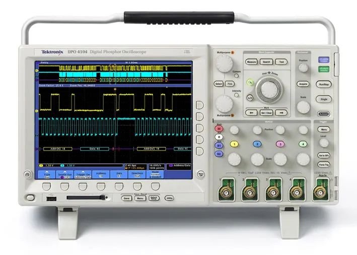
Parts of an Oscilloscope
The main parts of an oscilloscope are the display, the input, and the control panel. The display is usually a CRT or LCD screen that displays the waveform of the signal being measured. The input is the connector used to receive the signal being measured, such as a BNC or banana plug. The control panel is the collection of knobs and buttons used to control the oscilloscope.
The control panel typically includes knobs and buttons for adjusting the time base, voltage range, trigger level, and other settings. It also includes a selection of inputs, such as AC, DC, and ground, which can be used to measure different types of signals.
How to use an oscilloscope?
The oscilloscope has long been one of the most effective tools for testing electronic circuits. By observing the voltage and current waveforms of key nodes in the circuit, you can visually check whether the circuit is working normally and verify whether the design is appropriate. This is extremely helpful for improving reliability. Of course, the correct analysis and judgment of the waveform depends on the experience of the engineer himself.
Connecting and Setting up an Oscilloscope
The first step in using an oscilloscope is connecting it to the signal being measured. This is typically done with a coaxial cable, which is connected to the input of the oscilloscope and the signal source. Once the oscilloscope is connected to the signal, it’s time to set it up.
The setup of an oscilloscope is relatively simple. The first step is to adjust the time base, which determines how long it takes for the waveform to move across the screen. This is typically done with a knob on the control panel. Next, the voltage range should be adjusted, which determines the maximum voltage that can be measured. Finally, the trigger level should be adjusted, which determines when the waveform will start to be displayed on the screen.
Measure Voltage and Time Intervals
Once the oscilloscope is set up, it can be used to measure voltage and time intervals. To measure voltage, simply adjust the voltage range knob to the desired voltage range and then observe the waveform being displayed on the screen. The waveform should be an accurate reflection of the signal being measured, and the voltage can be read directly from the waveform.
To measure time intervals, adjust the time base knob to the desired time interval and then observe the waveform. The time interval can be read directly from the waveform, and can be used to measure the frequency of the signal being measured.
Troubleshooting with an Oscilloscope
Oscilloscopes are also useful for troubleshooting and debugging circuits. By connecting the oscilloscope to the circuit, it can be used to observe the waveform and identify any problems. For example, if the waveform is not displaying correctly, then it may indicate a problem with the circuit. Similarly, if the waveform is not within the expected range, then it may indicate a problem with the power supply or other components.
Working with Different Oscilloscope Waveforms
In addition to measuring voltage and time intervals, oscilloscopes can be used to measure a variety of waveforms. Different types of waveforms include sine, square, sawtooth, and triangle waveforms. By connecting the oscilloscope to a circuit and observing the waveform, it can be used to identify any problems with the circuit.
Different Types of Oscilloscopes
There are a variety of different oscilloscopes available on the market, each with its own unique features and capabilities. The most common types of oscilloscopes are analog, digital, and mixed-signal oscilloscopes.
Analog oscilloscopes are the most basic type of oscilloscope, and they are typically used for basic measurements. Digital oscilloscopes are more advanced and can measure more complex signals. Mixed-signal oscilloscopes are the most advanced type of oscilloscope and can measure both analog and digital signals.
Analog Oscilloscopes
An analog oscilloscope is a comprehensive test equipment displayed through a cathode ray oscilloscope. It can test the amplitude, frequency, period, phase and other parameters of the signal, and can also analyze the signal in time domain. Commonly used types include general purpose, dual trace, and dual scan.

Advantages
- Real-time bandwidth and real-time display
- Wide dynamic range
- Simultaneous multiple waveforms
- High bandwidth and accuracy
- Long memory storage
- Cost-effectiveness
- Easy to use and understand
- Provides an accurate display of signals
- Can be used to measure frequency, voltage, and other parameters
- Capable of displaying multiple signals
- Can capture hundreds of thousands of waveforms per second
- Easy to use and simple to understand
- Can be used to diagnose and troubleshoot electrical circuits
- Can be used to test various components and devices
- Support signals with low amplitude
- Support very fast changing and varying frequencies signals
- Can measure and observe multiple signals simultaneously
- Can be used for debugging and troubleshooting electronic circuits
Disadvantages
- Lower resolution than digital oscilloscopes
- Difficult to capture data accurately
- Higher likelihood of interference from external sources
- Not as user-friendly as digital oscilloscopes
- Limited bandwidth
- High noise levels due to the low-frequency signals
- Low input impedance
- Multiple traces can cause interference
- Complex setup and operation
- Limited memory capacity and slow sweep speeds
Digital Oscilloscope
A digital oscilloscope is a comprehensive test equipment that is first implemented through analog/digital conversion and then implemented with modern digital signal processing methods. In addition to the functions of an analog oscilloscope, it usually has functions such as data processing, storage, and transmission, and can also perform time-domain or even frequency-domain analysis on the measured signal. Commonly used digital storage oscilloscopes and sampling oscilloscopes.

Advantages
- Small size, light weight, easy to carry, LCD display
- Long time to store and analyse the waveforms
- Suitable for measuring single-shot and low-frequency signals
- No flickering phenomenon when measuring low-frequency signals
- More trigger methods: pre-trigger, logic triggers, pulse width triggers
- Powerful waveform processing capability
Disadvantages
- Expensive to purchase
- Complex to use for beginner users
- Longer setup time compared to analog oscilloscopes
- Limited dynamic range and rise time of digital oscilloscopes
- Noisy signals can cause errors in the readings
- Prone to electromagnetic interference
- High power consumption
- Limited frequency range
- Limited record length
- Difficult to diagnose low-level signals
- Prone to noise interference
- Require significant amounts of power
Oscilloscope Specifications
When purchasing an oscilloscope, it’s important to understand the specifications of the device. Different oscilloscopes have different features and capabilities, and understanding the specifications can help you choose the right oscilloscope for your needs.
The most important specifications to consider are the bandwidth, sampling rate, resolution, and input impedance. The bandwidth is the maximum frequency that the oscilloscope can measure, and the sampling rate is the speed at which the oscilloscope can measure the signal. The resolution is the accuracy of the waveform being displayed, and the input impedance determines how much voltage the oscilloscope can measure.
Tips and Tricks for Using an Oscilloscope
Using an oscilloscope can be a complex task, but there are a few tips and tricks that can help make it easier. One of the most important tips is to make sure that the input impedance is set correctly for the signal being measured. This will ensure that the oscilloscope can accurately measure the signal without being affected by outside noise or electrical interference.
Another tip is to make sure that the time base is set correctly. This will ensure that the waveform is displayed correctly on the screen. Finally, it’s important to adjust the trigger level correctly. This will ensure that the waveform is displayed at the right time and with the right amplitude.
FAQ
The real-time sampling rate is the reciprocal of the sampling interval of one acquisition (one trigger) of the oscilloscope. It is understood that the highest level in the industry is the simultaneous use of four channels.
The ratio of active power to apparent power is called power factor, which is represented by COSΦ. In fact, the simplest measurement method is to measure the phase difference between voltage and current, and the result is power factor.
Most modern digital oscilloscopes have FFT functions, and the above-mentioned systems can even pre-test current harmonics according to the EN61000-3-2 standard.
Holdoff (trigger holdoff) means to temporarily close the trigger circuit of the oscilloscope for a period of time (i.e. the holdoff time). During this period, the oscilloscope will not trigger even if there is a signal waveform point that meets the trigger condition. In the digital oscilloscope, it is also expressed as a percentage, which means the percentage of the entire record length or the entire screen.
The best way is to use a differential probe, the signal measured at this time is the most real and objective; if there is no differential probe, you can use two differential probes to connect to the two channels of the oscilloscope (such as Ch1, Ch2), and then use mathematics Calculate, get the waveform of ch1-ch2 and analyze it. At this time, try to keep the two probes exactly the same. The Vertical scale (how many volts per division) of the two channels of the oscilloscope is set the same, otherwise, the error will be large.
Bandwidth is the basic index of the oscilloscope. It is the same as the definition of the bandwidth of the amplifier. It is the so-called -3dB point, that is, the frequency point when the sine wave is added to the input of the oscilloscope and the amplitude attenuates to 70.7% of the actual amplitude is called the bandwidth. That is to say, using a 100MHz bandwidth oscilloscope to measure a 1V, 100MHz sine wave, the amplitude obtained is only 0.707V. This is only the case for sine waves. Therefore, when we choose an oscilloscope, in order to achieve a certain measurement accuracy, we should choose a bandwidth that is 5 times the highest frequency of the signal.
If the signal does exist, but sometimes the oscilloscope can catch it, sometimes it cannot, it may have something to do with the settings of the oscilloscope. Usually, if you can set the trigger mode of the oscilloscope to Normal, set the trigger condition to edge trigger, adjust the trigger level to an appropriate value, and then set the sweep mode to single mode, if this method does not work, usually the instrument may fail problem.
Conclusion
Using an oscilloscope can seem intimidating at first, but with a bit of practice, it can become second nature. By understanding the basics of how to use an oscilloscope, including parts of an oscilloscope, connecting and setting up an oscilloscope, using the oscilloscope to measure voltage and time intervals, troubleshooting with an oscilloscope, working with different oscilloscope waveforms, understanding oscilloscope specifications, different types of oscilloscopes, and tips and tricks for using an oscilloscope, it’s possible to quickly learn the basics and start making useful measurements.