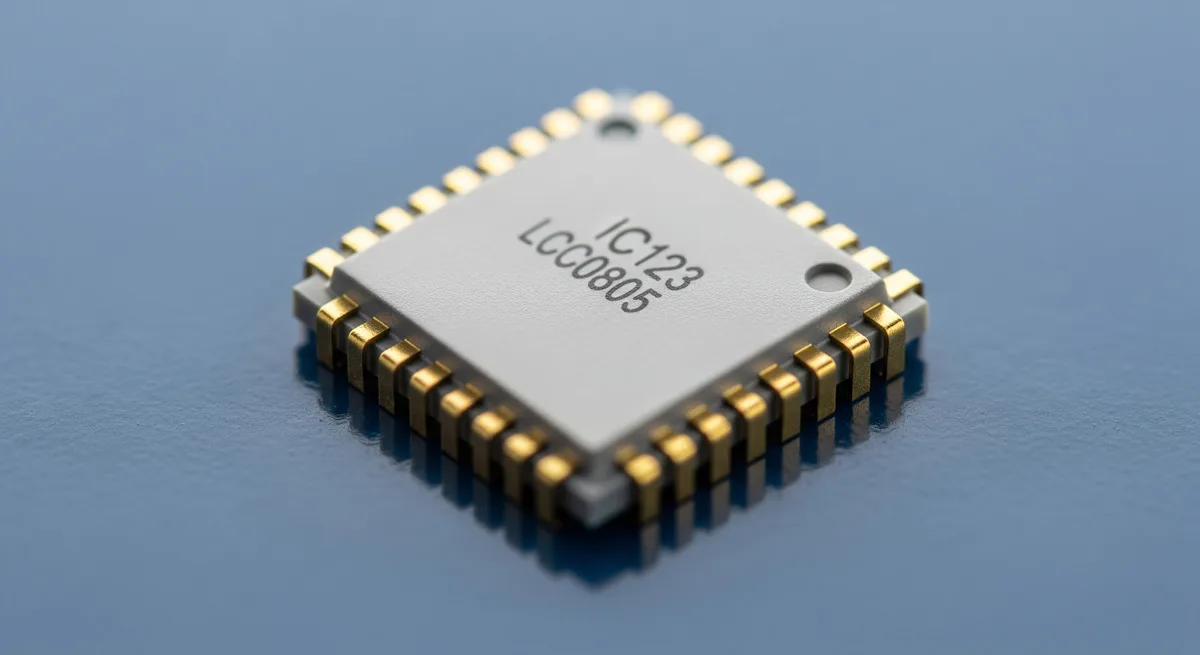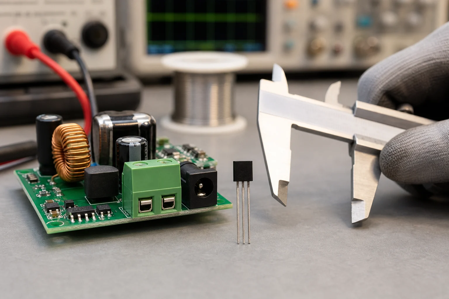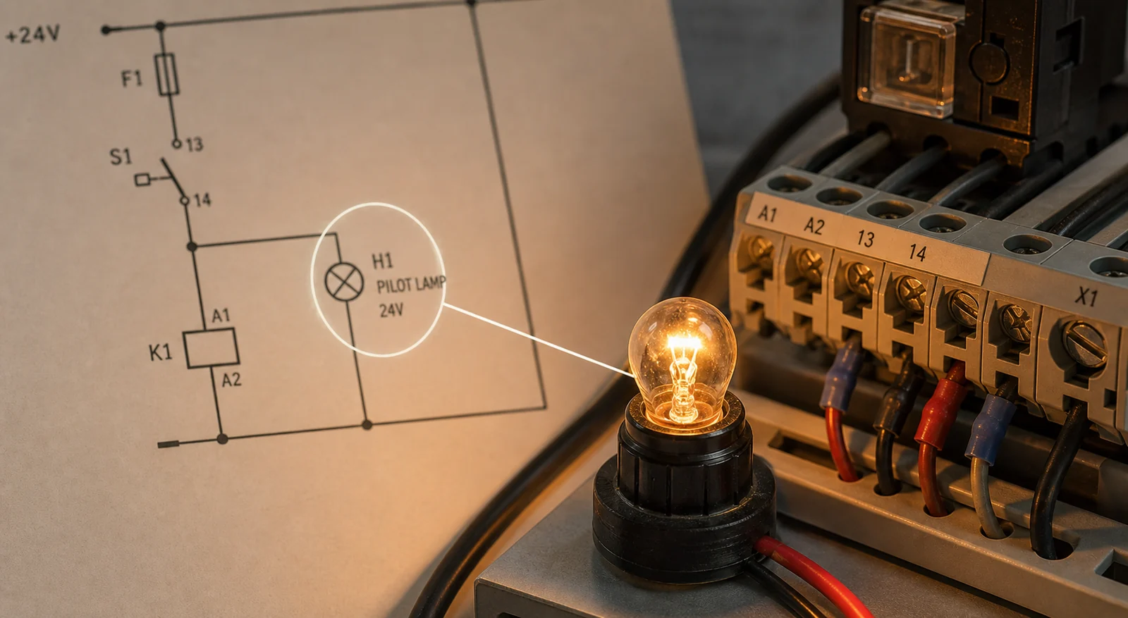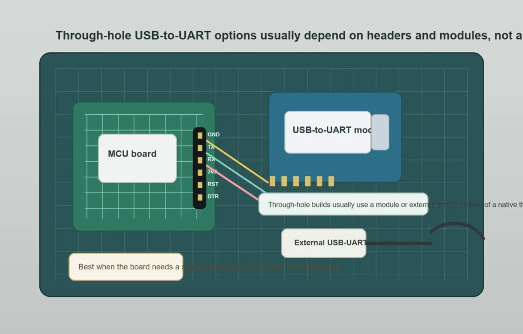
While a native through-hole (DIP) CP2102 IC would be ideal for hand-assembled boards, Silicon Labs offers the CP2102 family only in surface-mount QFN packaging. To implement a through-hole USB-to-UART interface, hardware designs must integrate a small CP2102 breakout module, standard 0.1-inch (2.54mm) headers, or an external USB cable rather than a direct-solder IC.
Surface-Mount vs. Through-Hole Strategies for CP2102 Integration
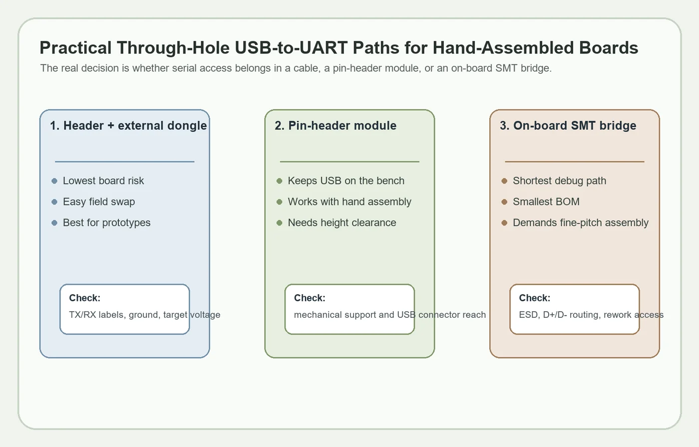
The CP2102 name refers to a USB-to-UART bridge device, but the device family is typically packaged for surface-mount assembly. That means a through-hole board designer is usually looking for one of three substitutes: a pin-header module built around the bridge, an external USB-to-UART adapter that connects to a header, or a redesign that keeps the bridge as an SMT part while everything else remains hand-assembly friendly.
This is the same tradeoff you see when comparing through-hole and surface-mount assembly constraints. The package decision changes more than soldering difficulty. It also changes debug accessibility, enclosure height, ESD exposure, connector strain, and how easy the board is to repair when a lab setup gets abused.
Comparing CP2102 Implementation Options for Prototypes and Production
If the board will only be programmed or debugged during bring-up, a 4-pin or 6-pin header plus an external dongle is often the cleanest choice. You keep USB connector wear off the target board, you avoid routing a bridge IC and crystal onto a low-volume assembly, and you can replace the adapter instantly if it fails. This is especially attractive for prototypes, lab fixtures, or educational boards that will be hand-soldered.
When a header plus external dongle is better?
Use this path when the product does not need a permanent USB connector, when enclosure space is tight, or when the team wants one known-good debug tool that works across several boards. It also keeps the board simpler if the main concern is field recovery or bootloader access rather than end-user USB communication.
When a pin-header module makes more sense?
A small module is helpful when the board really does need on-board USB-to-UART capability, but the assembly method is still mostly through-hole or bench-friendly. In that case, the bridge stays on a small sub-board and the main PCB only needs header pins or a socket footprint. You trade height and mechanical complexity for easier main-board assembly and easier replacement.
When to accept an SMT bridge on the board?
If the board is headed toward repeated builds, limited enclosure height, or more polished product behavior, an on-board SMT bridge can still be the better architecture. The trick is to isolate that decision from the rest of the hand-assembly pain: keep the layout clean, protect the USB lines, and avoid turning one small bridge IC into a full-board rework burden.
Board details Vs. bridge part number
Once serial access is on the board, several small design choices matter more than the brand name of the bridge. The first is voltage domain clarity. If the target UART is 3.3 V, the header, module, or dongle setup must make that obvious so nobody connects 5 V logic by habit. The second is labeling. TX, RX, GND, and optional reset or boot pins should be readable on the board without opening a PDF.
The next issue is reset behavior. Many workflows want DTR or RTS available so firmware download or auto-reset logic can be triggered cleanly. If that matters, route it on purpose and document it. Do not assume every external adapter exposes the same handshake signals or the same header order. Simple serial bring-up problems often come from mismatched pin order, floating grounds, or unlabeled reset intent rather than from the UART bridge itself.
Mechanical strain matters too. A USB cable plugged into a fragile daughter module can put a surprising amount of leverage into a pin header. If the board is likely to be debugged repeatedly, think about support posts, connector orientation, and whether the serial path should live off-board instead. Good through-hole soldering practice helps, but it does not remove poor mechanical decisions.
When to Use CP2102 in the design?
The most practical way to keep CP2102-class functionality in a through-hole-heavy build is usually to let the bridge live on a module or on a small SMT section of the board. That approach keeps the main target board easy to assemble while still giving you a known serial interface. It also respects the packaging reality that modern bridge ICs are optimized for surface-mount production, not for 0.1-inch through-hole footprints.
If you go on-board, treat it like a real USB design task. Protect the connector side, keep the routing tidy, and do not bury the bridge where it becomes impossible to rework. If you use a module, plan the keep-out and height stack so the module does not collide with shields, displays, or enclosure walls. Either way, the design succeeds when the debug path is intentional, not when the team chases a nonexistent through-hole version of the silicon.
conclusion
Ultimately, selecting the right CP2102 integration strategy comes down to balancing prototyping convenience with long-term manufacturability. For low-volume boards or test fixtures, offloading the USB-to-UART interface to a 2.54mm header module is often the cleanest, most repairable solution. For higher-density products, transitioning to a native SMT layout remains the standard path once reflow processes are in place. The best design prioritizes testability without letting packaging constraints compromise the overall hardware architecture.
FAQ
Is there a native CP2102 through-hole IC package for PCB assembly?
In normal practice, designers treat CP2102-class devices as surface-mount parts rather than true through-hole ICs. Through-hole-friendly builds usually rely on breakout modules, plug-in daughterboards, or an external USB-to-UART adapter connected to a header.
When is an external USB-to-UART dongle better than an on-board bridge?
It is usually better when the board only needs debug or bootloader access, when enclosure space is tight, or when you want one reusable lab tool across many prototypes. It also reduces rework risk because the target PCB does not need to carry the full USB bridge circuit.
What signals should a through-hole serial header expose?
At minimum, expose TX, RX, GND, and the correct logic voltage reference. If your firmware workflow needs it, also expose reset, boot mode, DTR, or RTS so programming and recovery steps are repeatable instead of depending on manual timing.
What is the biggest mistake when adding USB-to-UART access to a hand-assembled board?
The biggest mistake is focusing on the bridge part number while ignoring voltage domain, labeling, connector strain, and reset behavior. Most field failures and bring-up frustrations come from those interface details, not from the UART conversion function itself.