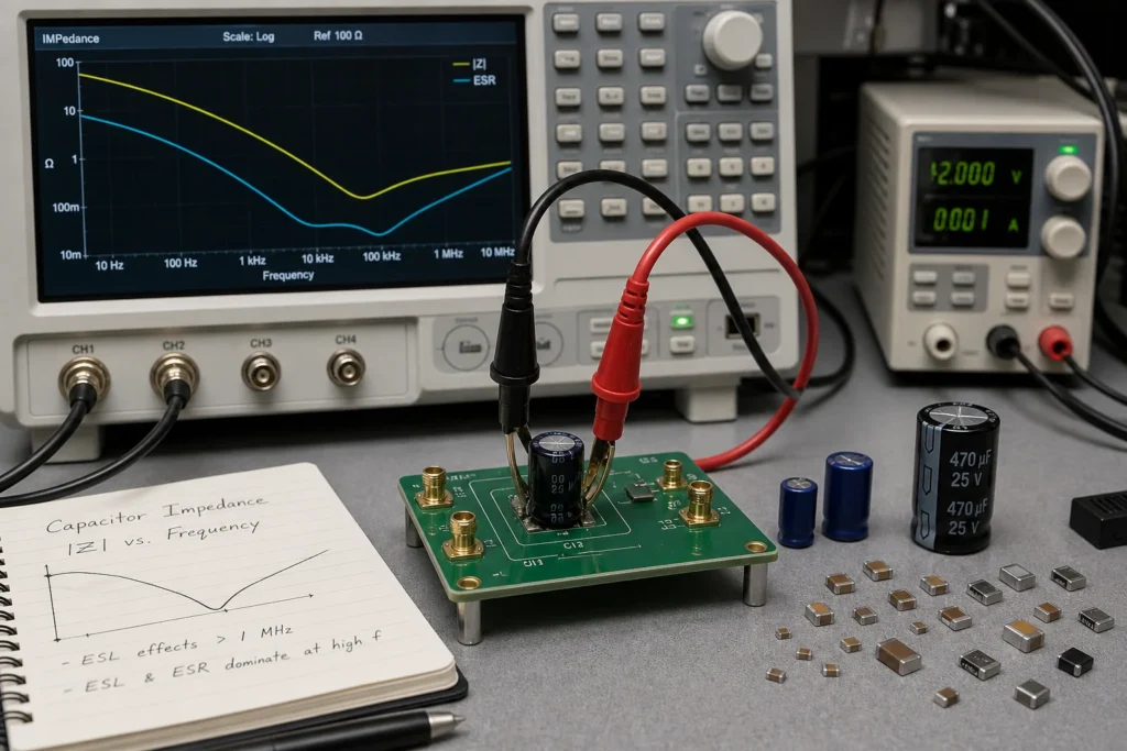
The impedance of a capacitor is usually introduced with a clean formula: Xc = 1 / (2?fC). That relationship is correct for an ideal capacitor, and it is still the right place to start. But it is not enough to explain how real capacitors behave on a board. Once equivalent series resistance, equivalent series inductance, dielectric loss, DC bias shift, and PCB mounting are involved, the usable impedance curve becomes a lot more interesting.
That distinction matters in power decoupling, analog filtering, timing networks, and stability work. Engineers who choose capacitors only by nominal capacitance often end up with parts that look right in the schematic and disappoint on the bench.
What the ideal formula gets right
In an ideal capacitor, impedance falls as frequency rises. Double the frequency and the capacitive reactance halves. Increase capacitance and the same frequency sees lower impedance. That is why capacitors can shunt AC ripple, set RC time constants, and provide local charge for switching loads.
At this level, the explanation is simple and useful. It also connects directly to filter and timing design, and to everyday troubleshooting with multimeter symbols during troubleshooting. But that ideal model starts to break down once frequency rises or current pulses become sharp enough that parasitics matter.
Why real capacitor impedance does not keep falling forever
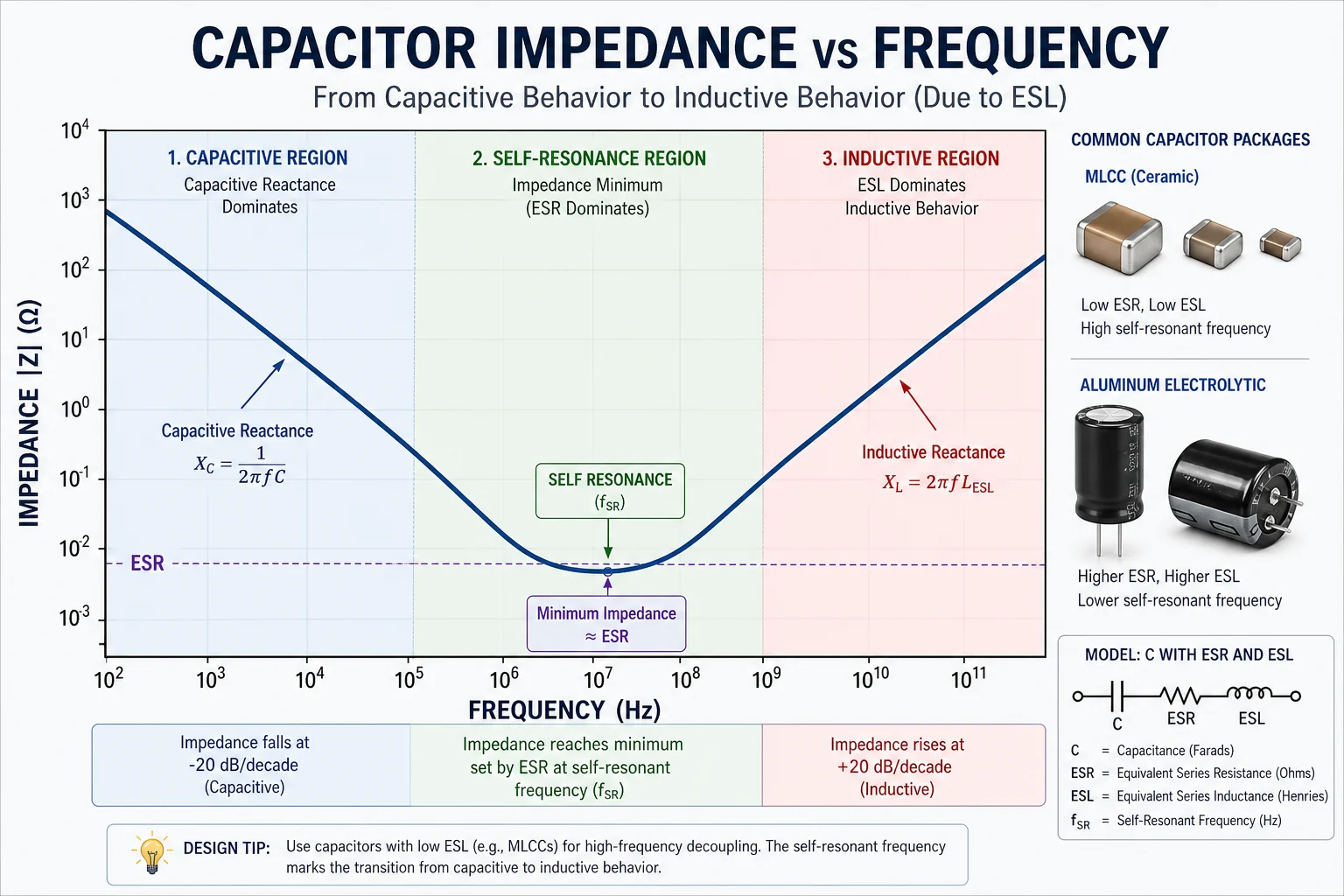
Every real capacitor includes ESR and ESL. ESR adds a resistive floor to the impedance curve. ESL adds inductive behavior that becomes more visible as frequency rises. Together, they create a self-resonant point where the capacitive and inductive effects balance. Below resonance, the device looks capacitive. Above resonance, it starts to look inductive.
This is why a higher nominal capacitance does not guarantee lower impedance at the frequency you care about. A large electrolytic may store more energy, yet a small MLCC mounted close to the load can outperform it for fast edge current because the package and connection inductance are dramatically lower.
Package, dielectric, and bias all change the answer
Capacitor impedance depends on more than capacitance value. Dielectric class changes loss behavior. Voltage rating affects physical geometry. Package size changes inductance. MLCC parts can also lose effective capacitance under DC bias, which shifts the impedance curve away from the catalog number. That is one reason a decoupling network that looks generous on paper can still underperform in a switching regulator or high-speed digital design.
These effects are especially important in circuits that need predictable loop behavior, such as transimpedance amplifier design or switching power stages near an LM2596 buck converter schematic. In those cases, the capacitor is part of a frequency-dependent system, not just a standalone value.
PCB mounting can dominate the practical impedance
Even a well-chosen capacitor loses advantage if it is connected badly. Long traces, narrow neck-downs, extra vias, or a distant return path add inductance that the datasheet did not include. In fast current loops, the board can contribute as much trouble as the component choice. That is why decoupling capacitors belong physically close to the pins they support, with tight current loops and minimal via penalty.
For repair and debugging, this also explains why a replacement capacitor with the same capacitance and voltage rating may still change behavior. Different package construction or lead length changes the impedance profile enough to affect ringing, converter stability, or noise.
Choose by frequency target, not by capacitance alone
A practical capacitor selection process starts with the frequency range that matters. Bulk energy storage, audio coupling, switching ripple, and digital bypassing do not ask the same thing from a part. Once the frequency target is known, the right question becomes: which part keeps impedance low enough in the region where this circuit needs help?
The impedance of a capacitor is therefore a curve, not a single number. Engineers who remember that point make better decisions about part type, package, placement, and parallel combinations. The formula still matters. It just needs to be anchored in real component physics and real PCB layout.
Why engineers often combine capacitor types in parallel
One common response to the impedance curve problem is to use more than one capacitor type in parallel. A bulk capacitor can handle lower-frequency energy demand, while a smaller low-ESL MLCC supports faster edges closer to the load. This is not magic stacking. It works only when each capacitor covers a different useful frequency region and the layout does not add enough parasitic inductance to erase the benefit.
Parallel networks also need judgment because anti-resonance can appear when parts interact. In sensitive power or analog work, the right mix is confirmed with simulation, impedance plots, or bench measurement rather than assumed from capacitance values alone. That is another reminder that capacitor impedance is a system behavior, not a catalog checkbox.
That is also why datasheet impedance plots are more useful than nominal capacitance alone when you are selecting decoupling or filter parts. The plot shows where the part is genuinely helpful and where mounting or parasitic limits begin to take over.