The best through hole soldering tricks are usually small process corrections, not magic hand skills. Most avoidable defects come from the same few mistakes: heating the lead instead of the joint, trying to fill a heavy barrel too fast, moving the board before the solder freezes, or staying on the pad long enough to start damaging resin and copper adhesion. Once those habits show up in rework, they turn a simple through-hole job into lifted pads, dull joints, and intermittent failures that are expensive to diagnose later.
If you build prototypes, repair industrial boards, or hand-solder low-volume assemblies, through hole soldering still matters because connectors, transformers, relays, high-current terminals, and mechanically stressed parts are often through-hole for a reason. The practical goal is not just to make the solder look shiny. It is to form a complete metallurgical joint without overheating the laminate or starving the plated barrel.
Start with joint geometry, not with solder volume
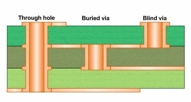
A common beginner mistake is treating through-hole soldering as “feed solder until the hole looks full.” That can hide poor wetting. The barrel, lead, and pad all need to reach soldering temperature together. If only the iron tip is hot, solder will pool on the lead or form a cap on the pad while the inside of the plated hole remains under-wet.
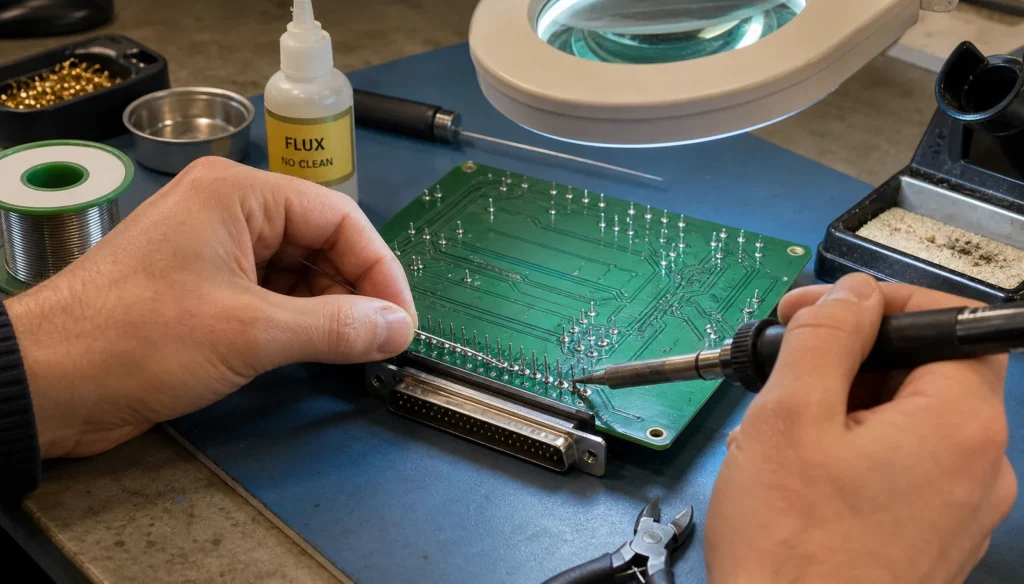
The first useful trick is to aim your heat where the lead and pad meet, then feed solder into that hot interface rather than onto the tip. When the joint is ready, solder should flow around the lead, wet the pad evenly, and form a smooth fillet without requiring a large blob. On multilayer boards with thick copper planes, give the barrel time to catch up. Rushing that step often creates a joint that looks acceptable from one side but fails under vibration or current load.
This is also where flux quality matters. If the joint keeps resisting wetting, adding more solder is usually the wrong fix. Clean chemistry and the right flux behavior do more for joint quality than brute-force dwell time.
Match the iron setup to the board’s thermal load
Through-hole work is unforgiving when the tool is too small for the copper mass. A narrow conical tip may be fine for signal headers, but it struggles on shield tabs, ground pins, and heavy connector leads tied into planes. The result is predictable: long dwell, scorched flux, and a board that gets hotter while the joint still does not wet correctly.
- Use a tip with enough contact area to transfer heat into both pad and lead.
- Raise thermal capacity before raising temperature. A better tip often solves the problem faster than a hotter station setting.
- Preheat difficult boards when large copper pours or heavy terminals keep stealing heat.
- Support the board so pressure on the iron does not flex the pad or crack an aging barrel.
For repair work, this matters even more because older boards may already have weakened pad adhesion from previous rework cycles. Aggressive dwell can turn a recoverable solder joint into trace repair.
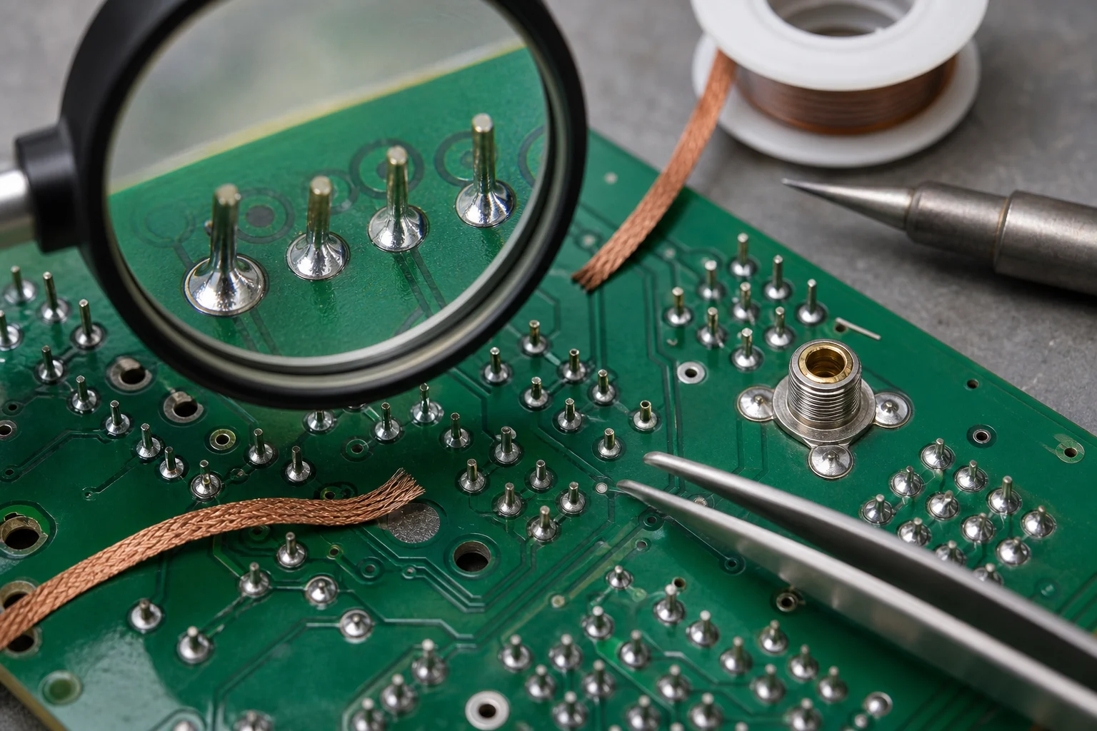
Use these through hole soldering tricks to avoid common defects
Feed less solder than you think you need
Overfilling is one of the most common avoidable mistakes. A correct joint does not need to bury the lead under a dome. Too much solder can hide poor wetting, make inspection harder, and complicate later replacement of the component. Aim for a fillet that proves wetting, not a shape that proves enthusiasm.
Trim leads after the joint cools, not during movement
If you clip or push the lead while the solder is still freezing, micro-cracks can form around the barrel interface. Let the joint settle first. Then trim cleanly with supported cutters so the mechanical shock does not lever against the pad.
Watch the exit side of the barrel on thicker boards
On double-sided and multilayer boards, the top side may look acceptable while the solder has not fully wetted through. If the assembly allows inspection on both sides, confirm that the solder has actually traveled the barrel. This is especially important for connectors, power resistors, and parts exposed to insertion force.
Use solder wick as a control tool, not as punishment
Solder wick is useful when a joint is overloaded or contaminated, but repeated aggressive wicking removes heat margin from the pad. If a joint needs to be redone, add fresh flux first, use the wick briefly, and stop before the laminate begins to discolor. A damaged pad is usually worse than a joint that needed one more controlled pass.
Know when a joint is weak even if it looks finished
Some through-hole defects are obvious: a disturbed joint, a solder bridge, or a lifted annular ring. Others are quieter. A joint can still fail because the solder never bonded cleanly to an oxidized lead, because the barrel wall did not wet fully, or because the lead was moving under strain from a connector body.
If the board will see vibration, cable force, or current cycling, inspect more critically. A connector pin on a control board is not the same as a lightly loaded resistor lead. Mechanical stress changes what “good enough” means. When in doubt, compare the joint against the failure symptoms discussed in this cold solder joint guide and rework it before the assembly is powered or shipped.
When through-hole soldering should not stay manual
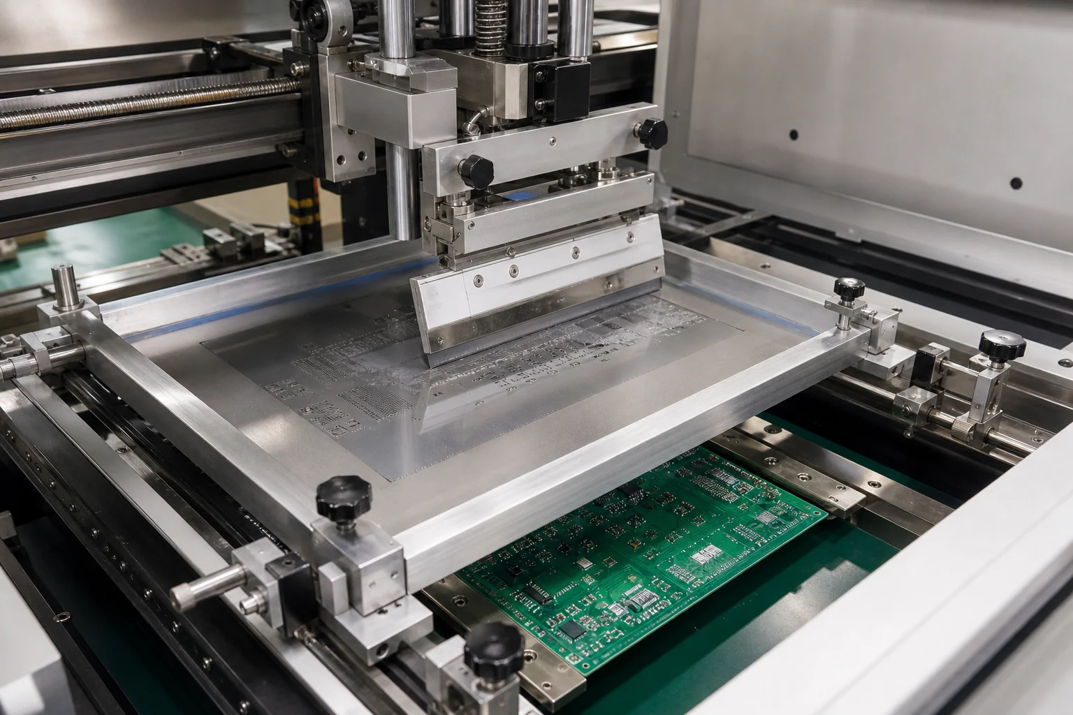
Another useful trick is knowing when to stop treating the problem as hand-solder work. If the board has dense mixed technology, high pin count connectors, or repetitive heavy joints, manual soldering may stop being the efficient option. Process variation climbs fast when one operator is carrying too much thermal decision-making. In those cases, a more controlled process or a design review may do more than asking for “better technique.”
That is where the broader tradeoff between through-hole and surface-mount assembly becomes practical instead of theoretical. The package style affects inspection access, mechanical reliability, and the amount of hand touch-up the product can tolerate.
The most useful through hole soldering trick is controlled heat
Good through hole soldering is rarely about speed. It is about controlled heat transfer, correct solder volume, stable handling, and enough inspection discipline to catch weak barrels before they become field faults. If you keep the joint geometry in mind and respect the board’s thermal load, the classic defects become much easier to prevent.
That is why the best through hole soldering tricks sound unglamorous: use the right tip, feed solder into the joint, support the board, verify barrel wetting, and stop reworking the same pad into failure. Those habits are what keep prototypes repairable and production joints reliable.
FAQ
What is the most important trick in through hole soldering?
Heat the pad and lead together, then feed solder into that interface instead of onto the tip. That single habit improves wetting, reduces blobs, and helps the solder fill the plated barrel correctly.
Why do through-hole joints still fail when they look shiny?
A shiny surface does not guarantee full barrel wetting or a strong bond to the lead. The joint may still be weak if heat never reached the full plated hole, if oxide contamination remained, or if the lead moved while the solder was freezing.
How do you avoid lifting pads during through-hole rework?
Use enough tip mass, add flux before rework, minimize repeated wick cycles, and let the board cool between attempts. Long dwell and repeated mechanical force are what usually break pad adhesion.
When is manual through-hole soldering the wrong process choice?
It becomes a poor fit when the board has many thermally heavy joints, dense mixed-technology layouts, or quality requirements that depend on tighter process repeatability than hand work can provide. At that point, process redesign or a more controlled assembly method is usually better than asking for faster manual soldering.