How many do you know about through hole vs surface mount? They are two ways to connect electronics components in pcb assembly (PCBA). They are cost-effective and reliable methods of connecting electrical components with conductive pads, wires or copper bumps. In this blog post, let’s explore the pros and cons of these different techniques to see which is best for your next project.
What is Through Hole Technology?
Through hole technology (or THT) is the process of connecting components by inserting wires through holes and soldering them to pads on the surface of a printed circuit board. Components are placed on the board and then wires are pushed through holes drilled in the board. The wires are then soldered to pads on the board. This was the most common way of connecting components on a printed circuit board (PCB) before surface mount technology (SMT) took over.

What is Surface Mount Technology?
Surface mount technology (SMT) is a process where components are placed on the surface of a printed circuit board and then connections are soldered to them. The components are mounted on the circuit board using an automated assembly machine. A computer controls the position of the components as they are placed on the board. A solder paste is applied to the board to connect the components. The components are placed on the board, and a squeegee is used to apply a thin layer of solder paste to the board. There are many benefits to SMT, including lower cost and less space needed in the circuit board.

Through Hole vs Surface Mount
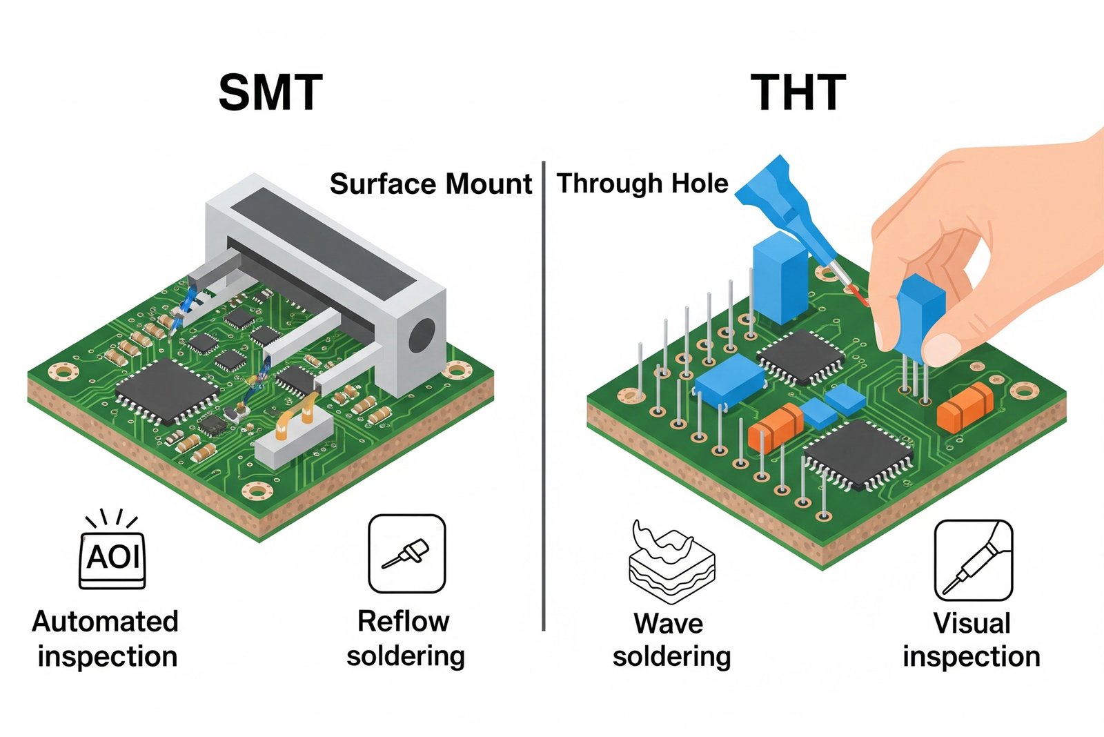
Through hole technology is a process that uses holes drilled in a printed circuit board. Wires are pushed into these holes, and then soldered to pads on the board. A diagram of a through hole connection is shown below. For a surface mount connection, components are placed directly on the board and then wires are soldered to them. A diagram of a surface mount connection is shown below. These two methods of connecting components both have their advantages and disadvantages. Let’s take a look at their pros and cons.
Advantages of Through Hole Technology
– High reliability – Through hole technology has been around for a long time. It has been used in almost every electronics device, making it very reliable.
– Ease of repair – Because the components are placed on a board with wires connecting them, they can easily be removed and re-soldered if needed.
– Ability to use larger components – Through hole technology is able to accommodate larger components that are not possible with surface mount. This is ideal for circuits with heavy current loads.
– More space on the PCB – With through hole technology, components use space on both sides of the board. This allows for more components on each board.
Advantages of SMT Technology
– Lower cost – Surface mount technology uses fewer materials than through hole, making it less expensive to manufacture.
– Smaller boards – It is possible to fit more components on each board using surface mount technology. This allows for smaller boards that take up less space.
– Easier to automate – Automated assembly machines can place the components on the board more precisely than humans.
– More flexibility in design – With surface mount technology, designers have more freedom to place components where they want on the board.
–Lower Power Requirements – Mechanical properties allow surface mount components to be very small, minimizing power consumption. Also, it allows BGAs to reduce IC trace length requirements since the leads can be soldered under the component.
Disadvantages of Through Hole Technology
– More time consuming to make – The process used in through hole technology is more manual than surface mount. This means the boards will take longer to manufacture.
– More expensive to make – The cost of a printed circuit board that uses through hole technology is higher than a board made with surface mount technology.
– Less density – When using through hole technology, there are limitations as to how many components can fit on each board because of the space needed for wires.
– Less design flexibility – Because of the limitations mentioned above, designers are less likely to use through hole technology for large boards.
– More chance of short circuits – While the chance of short circuits is less when using through hole technology, it is still possible. Wires can touch each other or other conductive parts.
Disadvantages of SMT Technology
– Design is more limited – With surface mount technology, there are limitations as to where components can be placed on the board. This is because wires need to be short enough to reach other components.
– More chance of short circuits – Although short circuits are less likely because of the single-sided connections, they are still possible.
– Less space on the board – Because the components are placed on one side of the board, designers have less space to use.
– More manual process – Components are placed one at a time with a human placing them on the board. This is a more manual process than through hole technology, which can be done with an assembly machine.
Conclusion
SMT cannot entirely supplant through-hole mounting in assembly. These two methods have their own advantages for the end user. In general, SMT is more space- and cost-effective. THT has greater resistance to mechanical, electrical, and thermal stresses.