In electronics, various abbreviations are used to represent different power supply voltages, such as VCC, VDD, VEE, VSS, and GND. Understanding the differences between these power supply voltages is crucial in designing and troubleshooting electronic circuits. In this post, we will delve into the definitions, characteristics, and usage of VCC, VDD, VEE, VSS, and GND to help you gain a better understanding of their roles in electronic circuits.
Definition of VCC, VDD, VEE, VSS, GND
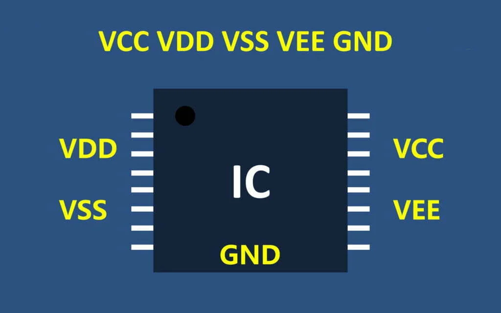
- VCC: C=circuit means the meaning of the circuit, that is, the voltage connected to the circuit
- VDD: D=device means the meaning of the device, that is, the internal working voltage of the device;
- VEE: negative voltage power supply; the source of the field effect tube (S)
- VSS: S=series means common connection, usually refers to the circuit common ground voltage
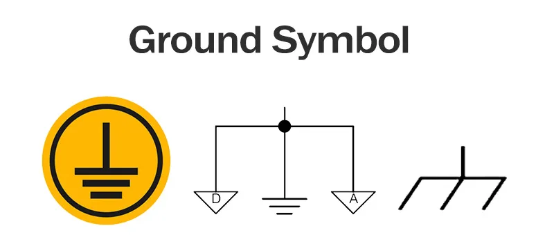
- GND: It is often defined as the voltage reference point in the circuit.
Others Related Label:
- VBAT: When a battery or other power supply is used to connect to the VBAT pin, when VDD is powered off, it can save the contents of the backup register and maintain the function of the RTC. If no external battery is used in the application, the VBAT pin should be connected to the VDD pin.
- VPP: programming/erasing voltage.
The difference between V and VA is: the difference between digital and analog.
The difference between CC and DD is: the difference between the power supply voltage and the working voltage (usually VCC>VDD).
Application Explanation
- For digital circuits, VCC is the power supply voltage of the circuit, VDD is the working voltage of the chip (usually Vcc>Vdd), and VSS is the ground point. For example, for ARM single-chip microcomputer, its power supply voltage VCC is generally 5V, which is generally converted into the single-chip microcomputer working voltage VDD = 3.3V by a voltage stabilization module.
- Some ICs have both VDD and VCC pins, which means that the device itself has a voltage conversion function.
- In the field effect transistor (or COMS device), VDD is the drain, VSS is the source, VDD and VSS refer to the component pins, not the power supply voltage.
- Generally speaking, VCC=analog power supply, VDD=digital power supply, VSS=digital ground, VEE=negative power supply.
- In the electrical sense, GND is divided into power ground and signal ground. PG is the abbreviation of Power Ground (power ground). The other is Signal Ground (signal ground). They may actually be connected (not necessarily mixed!). The two names are mainly to facilitate the analysis of the circuit.
Furthermore, there are two “grounds” that must be distinguished due to different circuit forms: digital ground and analog ground. Both digital ground and analog ground have signal ground and power ground. Between the digital ground and the analog ground, some circuits can be connected directly, some circuits need to be connected with a reactor, and some circuits cannot be connected.
Different Types of GND
There’re many different types of GND (Ground) in circuit, such as signal ground, protective ground, and audio ground.
Signal Ground
Signal “ground”, also known as reference “ground”, is the reference point of zero potential and the common segment that constitutes the circuit signal loop, symbolized by “⊥”.
- DC Ground: the reference point of zero potential in a DC circuit.
- AC Ground: the zero line of an AC power supply, which should be distinguished from the earth ground.
- Power Ground: the reference point of zero potential for high current network devices and power amplifiers.
- Analog Ground: the reference point of zero potential for amplifiers, sample and hold circuits, A/D converters, and comparators.
- Digital Ground: also called logic ground, is the reference point of zero potential for digital circuits.
- “Hot Ground”: for switch-mode power supplies that do not require transformers, the “ground” of the switching circuit is related to the AC power grid and is also known as “hot ground”. It is live and carries current.
- “Cold Ground”: the output ground of a switch-mode power supply is called “cold ground” as it is isolated from the input ground by a high-frequency transformer and optocouplers are used in the feedback circuit for transmitting signals while isolating the two sides’ grounds. It is not live.
Protective Ground:
Protective “ground” is a wiring method designed to protect people’s safety. One end of the protective “ground” wire is connected to the electrical appliance, and the other end is reliably connected to the earth. Devices such as the Earth Leakage Circuit Breaker (ELCB) are crucial for enhancing this protection by detecting and tripping in case of leakage currents.
Ground in Audio Systems:
- Shielding Ground: to prevent interference in audio systems, the metal casing of the audio equipment is connected to the signal “ground” via a wire, which is called shielding ground.
- Audio-specific Ground: in professional audio systems, in addition to shielding ground, it is necessary to connect to the audio-specific ground to prevent interference. This grounding device should be buried separately and connected to the corresponding grounding terminal of the isolation transformer and the shielding type stabilized power supply to serve as a dedicated audio ground point in the sound control room.
Engineering checks for VCC, VDD, VEE, VSS, and GND power naming
Before using VCC, VDD, VEE, VSS, and GND power naming in a PCB, firmware, repair, or validation workflow, confirm the details that usually decide whether the design works reliably instead of only reading the headline specification.
Design and troubleshooting checklist
| Area | What to check | Why it matters |
|---|---|---|
| Naming convention | Map each supply label to voltage, polarity, domain, and component family | Legacy bipolar and CMOS naming can mean different things on mixed boards |
| Schematic review | Check net ties, analog/digital ground, split rails, and connector labels | Incorrect power naming creates assembly and debug errors |
| Measurement | Verify each rail at startup, reset, sleep, and maximum load conditions | A label is not enough; measured rail behavior proves the design |
These checks help connect the search intent around VCC VDD GND meaning with practical board-level decisions, component selection, and failure analysis.