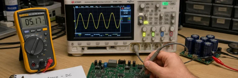
Impedance Versus Resistance in PCB Work Is Really a Question of Frequency
Resistance explains static loss and voltage drop, but impedance decides how PCB traces, capacitors, drivers, and interconnects behave once frequency and edge rate matter.

Resistance explains static loss and voltage drop, but impedance decides how PCB traces, capacitors, drivers, and interconnects behave once frequency and edge rate matter.
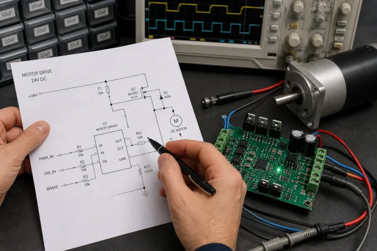
A motor schematic symbol only becomes useful when you read it with the power path, control method, and protection details that surround the load.
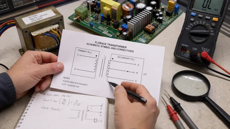
A transformer schematic symbol only helps when it makes winding polarity, taps, isolation, and real circuit intent clear enough for layout, test, and repair work.

An Altium net tie is useful when two nets must meet at one intentional location without losing their names, rules, or review visibility everywhere else.
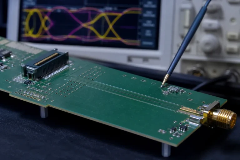
Impedance mismatch on a PCB usually appears first at the launch, via field, connector, or return-path break where the signal stops seeing the geometry you modeled.
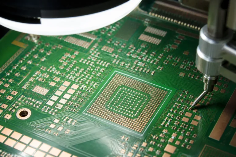
PCB solder mask thickness matters when it starts changing pad definition, inspection clarity, outer-layer impedance assumptions, and the assembly window around dense features.
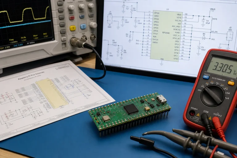
A Pi Pico schematic is most useful when it clarifies the power path, flash boot, USB behavior, and debug access that decide whether an RP2040 board starts cleanly.
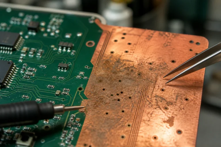
A PCB without solder mask can oxidize, stain, bridge during assembly, and become harder to inspect or rework unless the exposed copper area is intentional and tightly controlled.
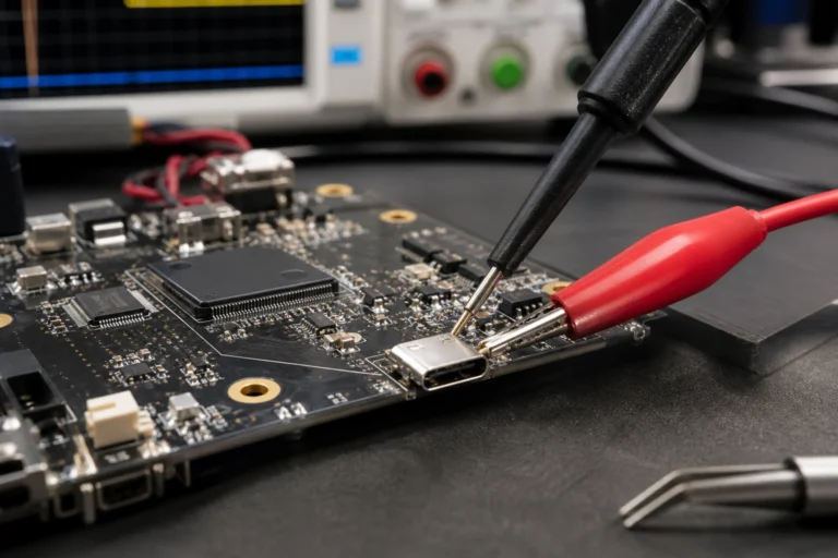
A USB wiring schematic is only useful when it shows connector role, VBUS handling, D plus and D minus routing, shield grounding, and the CC or ID details that affect a real PCB.
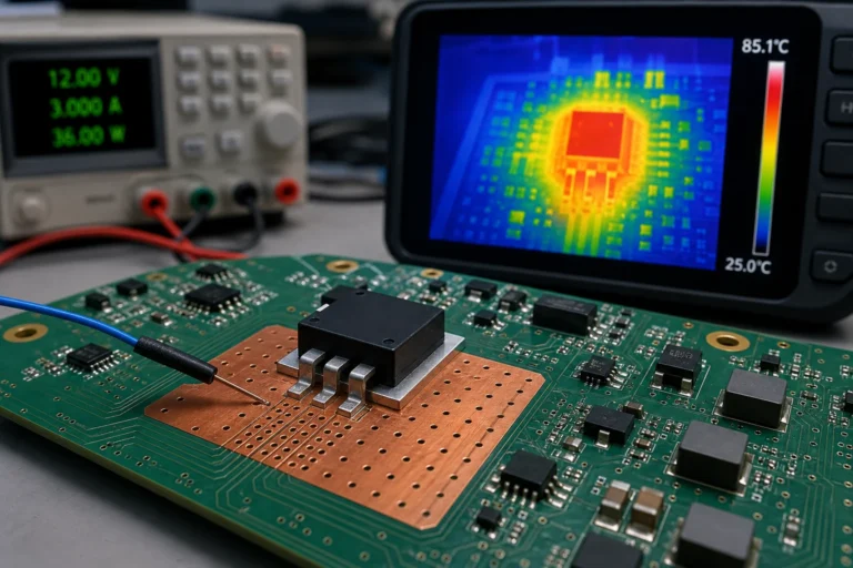
Thermal impedance is only useful when you know whether the datasheet number describes a package test board, a case path, a board path, or a short pulse event in your real design.
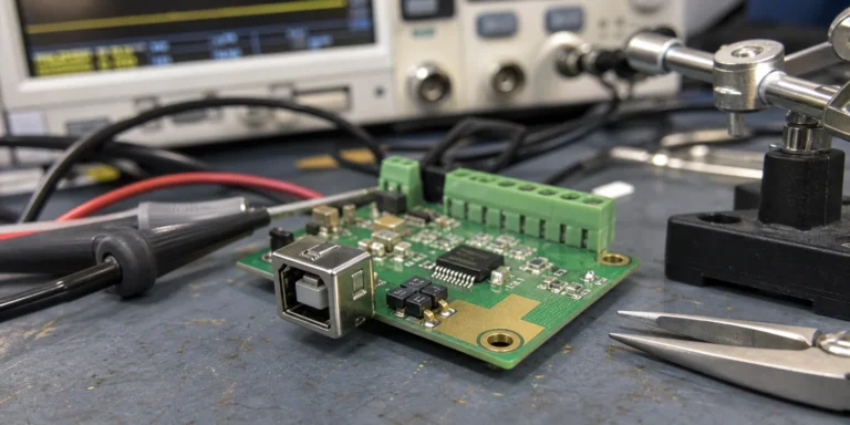
A TVS suppressor diode only protects a PCB when standoff voltage, clamp behavior, surge energy, and layout placement match the actual threat at the connector.
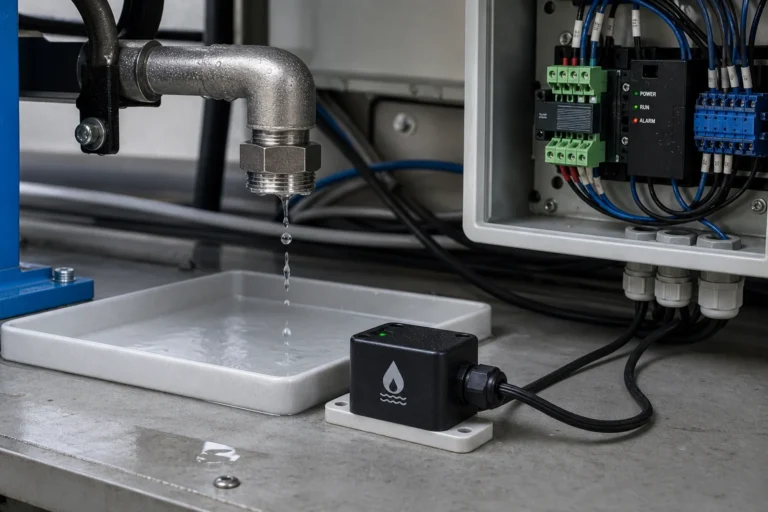
A water leak sensor works reliably only when probe corrosion, false alarms, placement, debounce, and shutoff logic are planned before release.