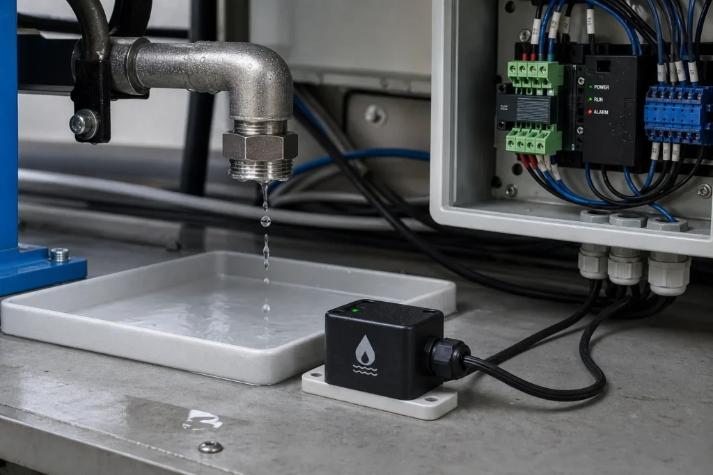
A water leak sensor looks simple until it has to survive flux residue, cable noise, cleaning chemistry, and the difference between a small drip and a real flooding event. For a hobby alarm on a basement floor, a cheap probe module may be enough. For a control cabinet, HVAC condensate tray, server room, or equipment enclosure, the wrong sensing method can create corrosion, nuisance trips, or a silent failure that shows up only after damage is already done.
This guide explains how to choose a water leak sensor from an engineering point of view. It focuses on the parts product teams usually underestimate: resistive versus capacitive sensing, PCB contamination risk, placement, interface choices, and the tests that should happen before the first production release.
What a water leak sensor is really detecting
A water leak sensor does not detect “water” in the abstract. It detects a change in conductivity, capacitance, or mechanical state that the circuit interprets as a leak event. That distinction matters because the sensing principle determines how quickly the system reacts, how often it false-triggers, and how much maintenance it needs.
Most practical leak-detection designs fall into three families. Resistive probe sensors look for a drop in resistance between exposed conductors when water bridges them. Capacitive sensors detect a dielectric change and can often work through a non-conductive wall or coating. Cable-style systems extend the detection path along trays, pipes, or raised-floor routes where a point sensor would miss the first leak.
If the installation environment includes mineral residue, cleaning chemicals, or condensation, the sensing method becomes a reliability decision rather than a feature comparison. That is why the right keyword-level question is not only “which water leak sensor should I use,” but “which sensing principle still works after months of exposure, contamination, and service conditions.”
Choose the sensing method by failure mode, not by module price
The cheapest sensor is often the most expensive choice after field maintenance, probe replacement, or false-alarm troubleshooting. Start with the failure mode you must catch and the environment the sensor has to live in.
Resistive probe sensors fit simple wet-contact detection
Resistive sensors are useful when you need direct contact detection at the lowest hardware cost. They are common under appliances, in drip pans, and in low-cost embedded alarms. The circuit is simple, the response can be fast, and integration with a microcontroller or comparator is straightforward.
The tradeoff is probe exposure. Bare electrodes can corrode, plate, or drift when DC bias is left on the sensor for long periods. Residue from assembly, hard-water minerals, or conductive dirt can also pull the measured resistance in the wrong direction. In other words, the circuit may still power up normally while the sensing threshold quietly becomes unreliable.
For that reason, a resistive design is safer when the excitation is duty-cycled or AC-coupled, the threshold has hysteresis, and the maintenance plan includes cleaning or probe replacement. If the product will be sealed and ignored for years, the simplest probe board may be the wrong long-term choice.
Capacitive sensors reduce corrosion but raise calibration demands
A capacitive water leak sensor avoids direct conductive contact and can detect moisture through plastic walls, adhesive layers, or enclosure surfaces. That is attractive in products where exposed metal would corrode or where you want to isolate the sensing element from contaminated liquid.
The engineering cost moves from electrode wear to calibration and layout control. Electrode geometry, ground reference, cable routing, shielding, and environmental drift all affect the baseline. A capacitive design that looks stable on the bench can become noisy once it sits next to a switching supply, long harness, or metal chassis.
Capacitive sensing is usually the better fit when maintenance access is poor, contamination is expected, or the installation requires non-contact detection. It is not automatically the easier design. The analog front end and validation plan need more discipline than many low-cost modules suggest.
Cable sensors work when the leak path is longer than one sensor footprint
If the real risk is water tracking along a pipe run, raised floor, or equipment perimeter, a point sensor may not see the first failure. Detection cable or distributed sensing is often better because it watches a route instead of one puddle location.
This changes the electronics problem. Cable length adds capacitance and noise pickup, connector quality matters more, and serviceability becomes part of the design. The right question is no longer only detection sensitivity. It is whether the system can still identify the event source and stay stable after the cable ages, gets cleaned, or is moved during maintenance.
PCB design mistakes that create false alarms or missed leaks
Many leak-sensor products fail because the board around the sensor was treated like a generic low-speed PCB. The sensor circuit is usually simple, but the parasitics and contamination paths around it are not.
Keep high-impedance sensing nodes away from switching regulators, relay coils, long PWM edges, and unguarded connector entries. If the design uses exposed probes, make sure there is enough creepage around the measurement path that ordinary dirt and residue do not imitate a wet event. Flux residue under a connector or around the front-end input can look like a weak leak long before the customer ever sees water.
Threshold logic also matters. A hard comparator threshold without hysteresis is a common source of chatter when drops form, evaporate, or partially bridge the sensor. Debounce is not just a firmware convenience. It is part of the sensing definition. Decide whether the product should respond to one conductive bridge, sustained wetting for several seconds, or a trend over time.
If the sensor cable leaves the board, protect that entry like any other field wiring. ESD, surge coupling, and ground potential shifts can all masquerade as a leak event. For industrial or building-integrated designs, a dry-contact output or isolated interface may be more robust than sending a raw analog signal across a long harness.
Placement matters as much as the circuit
A water leak sensor only works when the first escaped water reaches the sensing zone before it damages something else. That makes placement an engineering decision, not a packaging afterthought.
Place sensors at the first credible collection point: under a fitting, inside a condensate tray, beside a pump seal, below a filter housing, or along the edge where water will actually track. If the housing stands slightly above the floor, a shallow leak can flow around it instead of touching the electrodes. If the sensor is too close to washdown spray or routine cleaning, you may be designing in nuisance alarms.
For appliance or building systems, think about what happens after detection. Does the system only sound an alarm, or does it close a valve, stop a pump, or notify a controller? The output architecture should be chosen early. Relay outputs, open-collector alarms, analog thresholds, and MCU-based reporting all create different validation and fail-safe requirements.
This is also where internal links can help related ReversePCB readers. If the leak-sensor board is still in prototype, it is worth applying the same first-build discipline described in PCB prototype first-build risk planning. If the installation environment is harsh, coating and residue decisions need the same attention discussed in PCB conformal coating and post-solder cleaning risk.
How to test a leak sensor before release
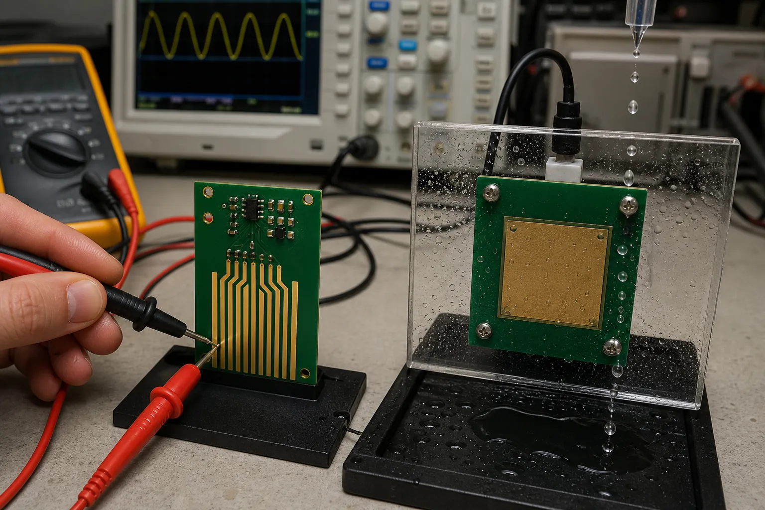
A credible leak-sensor validation plan needs more than dipping the probe in water once and watching an LED turn on. Test the conditions that create field confusion: condensation, intermittent dripping, mineral residue, detergent film, cable movement, low battery voltage, and recovery after the liquid dries.
For a resistive design, compare clean water, hard water, and contaminated water because the trigger margin can change substantially. For a capacitive design, test different wall thicknesses, mounting adhesives, and enclosure materials. If the product will be installed in an HVAC or industrial setting, temperature cycling and humidity soak matter because baseline drift may appear only after the board absorbs moisture.
Also decide what “recovered” means. Some products should auto-clear when the area is dry again. Others should latch until someone inspects the site. A sensor that repeatedly clears and retriggers during evaporation can create support problems even when the electronics technically behave as designed.
Before release, include at least one test that checks maintenance reality. Ask whether a technician can replace the sensor, clean the probes, inspect the cable, and verify the alarm path without taking apart half the product. If that answer is no, the design may be electrically correct but operationally weak.
When a standard module is enough and when a custom design is better
A module is usually enough for quick alarms, lab tools, and low-risk monitoring where replacement is easy. It is rarely enough for products that need controlled thresholds, long service life, harsh-environment stability, or integration with shutoff logic and system diagnostics.
A custom board makes sense when the sensor must fit a tight mechanical space, survive cleaning chemistry, pass compliance review with the rest of the system, or distinguish between condensation, splash, and sustained leakage. That is especially true when the product also needs event logging, power management, remote reporting, or a serviceable cable architecture.
If the design choice feels uncertain, narrow the decision to three questions: what leak must be caught first, what contamination or noise will the sensor see in normal use, and what action must the system take after detection. Those answers usually make the right sensor architecture clearer than comparing module catalogs.
Conclusion
The best water leak sensor is not the one with the loudest alarm or the lowest BOM cost. It is the one whose sensing method, PCB layout, placement, and recovery behavior match the real installation. For simple wet-contact alerts, a resistive sensor may be enough if corrosion and contamination are managed. For sealed products or dirty environments, capacitive or cable-based approaches usually justify their extra design effort.
When the design is reviewed early, the sensor becomes a useful protection layer instead of another field-return mystery. That is the difference between a leak detector that merely reacts to water and one that keeps a board, enclosure, or system from failing in the first place.
FAQ
Is a resistive water leak sensor always the cheapest option?
A resistive water leak sensor is usually the cheapest to build, but not always the cheapest to own. Exposed probes can corrode, collect residue, or drift over time, so field maintenance and nuisance alarms can erase the initial BOM savings.
When is a capacitive water leak sensor a better choice?
A capacitive design is usually better when the sensor must avoid exposed metal, detect through a non-conductive wall, or survive contamination that would change a resistive reading. It needs tighter layout control and calibration, but it often reduces long-term corrosion risk.
Why do water leak sensors generate false alarms on real products?
False alarms often come from residue on the PCB, cable noise, missing hysteresis, poor placement, or a threshold that was only tested with clean bench water. The sensing circuit may be simple, but the installation environment changes the effective behavior.
Should a leak sensor automatically reset after the area dries?
That depends on the application. For consumer alerts, auto-reset may be acceptable. For industrial equipment, condensate trays, or any installation where a real leak must be inspected, a latched alarm is often safer because it prevents brief wet events from disappearing before maintenance sees them.