Thermal impedance looks simple on a datasheet until a board that passed bench checks starts running hot in the enclosure. The problem is usually not the math alone. Engineers often apply a convenient thermal number to the wrong heat path, the wrong board condition, or the wrong power profile. That can turn a package that looked safe in review into a part that drifts, throttles, or ages early in production.
This guide explains what thermal impedance really tells you, which datasheet metrics are safe to use, and how to translate them into a PCB decision that survives layout, assembly, and field conditions.
Why thermal impedance causes expensive mistakes
Thermal impedance is a measure of how much temperature rise you get for a given amount of power flowing through a thermal path. In electronics work, that path is rarely just the silicon package. It usually includes copper area, vias, solder voiding, airflow, enclosure restrictions, nearby hot parts, and whether the board is mounted vertically, horizontally, or against metal.
The mistake is treating every thermal number as if it predicts the same thing. A junction-to-ambient value from a JEDEC test board may be useful for comparing package options, but it is not a promise that your actual PCB will rise by the same number of degrees per watt. Once the copper balance, layer stack, airflow, or mounting conditions change, the real path changes too.
Start with the heat path you actually own
Before comparing thermal figures, define where the heat is supposed to go. A regulator with an exposed pad wants heat pulled into the board. A MOSFET under a clip-on heatsink may rely more on the case path. A short pulse load may be governed by transient thermal behavior instead of steady-state junction-to-ambient resistance.
That is why thermal impedance should be read backward from the system. Ask these questions first:
- Is the dominant path board copper, package top, chassis contact, or forced air?
- Is the load continuous, bursty, or highly cyclical?
- Will assembly variation such as voiding under an exposed pad change the path?
- Will nearby hot devices raise the local ambient around the part?
If those answers are not clear, the best-looking thermal metric on the datasheet can still push you toward the wrong package or layout.
The thermal metrics engineers mix up most often
Not every thermal number answers the same design question. Keeping the roles separate prevents most early mistakes.
RθJA is useful for comparison, not blind prediction
Junction-to-ambient thermal resistance is the figure most engineers recognize first. It helps compare packages under defined test conditions, but it is heavily influenced by the test board and airflow assumptions. If your product uses smaller copper pours, denser placement, or a closed plastic enclosure, your effective result can be much worse than the datasheet number suggests.
RθJC and case-related numbers matter only if the case path is real
Junction-to-case values become useful when heat is intentionally extracted through the package top, tab, or mounting surface. They are often overused on parts that actually dump most heat into the PCB. If the package top has no meaningful thermal interface to a heatsink or chassis, a strong RθJC number may look comforting while doing very little for the finished assembly.
ΨJT and ΨJB help estimate junction temperature from measurements
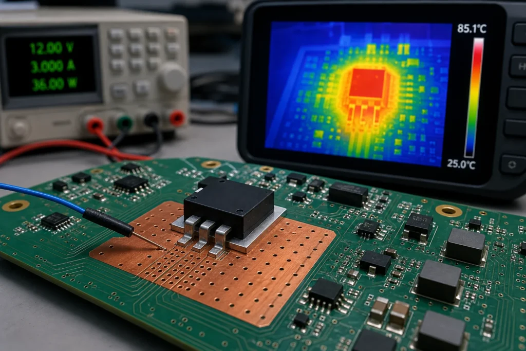
These characterization parameters are often more practical during validation because they help relate a measurable top-of-package or board temperature to the hidden junction. They are not interchangeable with thermal resistance values, but they are useful when you are on the bench with a thermocouple, a thermal camera, and a real board that does not match the datasheet coupon.
Transient thermal impedance matters when the power is not constant
Steady-state thermal resistance can hide short-duration stress. Motor drivers, hot-swap circuits, LED current pulses, and surge-handling semiconductors may survive average power yet still hit unsafe junction temperatures during bursts. In those cases, transient thermal impedance curves matter more than a single steady-state number.
What changes on a real PCB before the datasheet number means anything
A board-level thermal path is shaped by design and manufacturing details that are easy to underestimate during schematic review.
Copper area is the obvious factor, but copper continuity matters just as much. A large pour broken by slots, neck-downs, clearance islands, or sparse via stitching will not spread heat like a clean plane. Layer transitions matter too. If the exposed pad only touches top copper with weak via escape into inner and bottom planes, the package may run far hotter than expected.
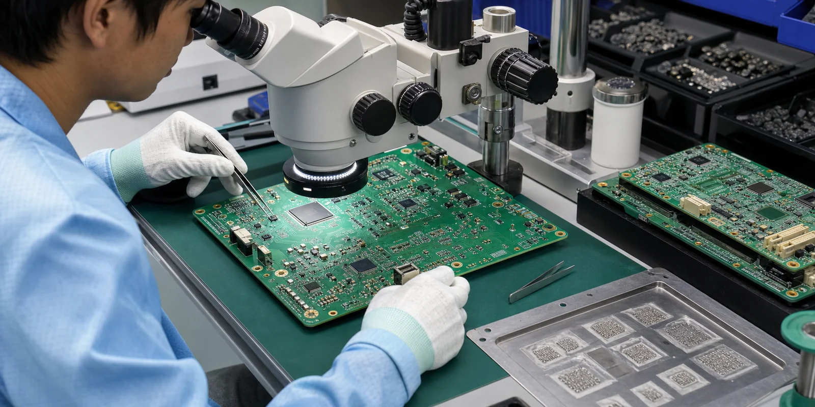
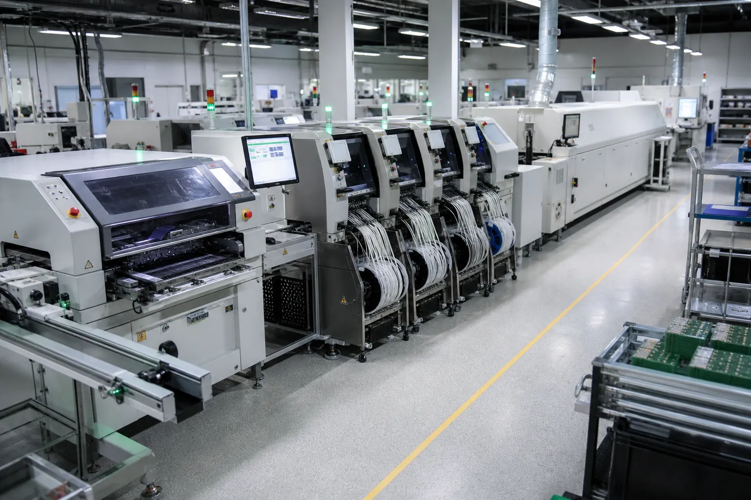
Assembly quality also changes thermal impedance. Voids under thermal pads, insufficient solder wetting, warped packages, and poor planarity all add resistance between the die path and the board. That is one reason a prototype can behave acceptably while production boards show wider thermal spread. Layout review and assembly process review have to meet in the same conversation.
Stackup choices influence the result as well. A board with thin copper and sparse internal planes sheds heat differently from one built around heavy copper and stitched reference planes. If the part sits near a BGA, transformer, or power resistor, local heating can also raise the true ambient around the package. In that situation the thermal equation is no longer about one component by itself, which is why a standard PCB stackup still needs thermal review when power density changes.

Where teams get thermal impedance wrong in practice
One common failure mode is choosing a package from the datasheet table without checking how much copper the part actually receives in the final placement. A regulator placed at the board edge near a connector often loses spreading area, and the cable entry region may already run warm from surge, inrush, or current density.
Another mistake is trusting simulation or spreadsheet estimates without checking process limits. A thermal pad filled with vias can work very well, but not if the via pattern steals paste, causes uneven collapse, or drives voiding high enough to break the intended heat path. The thermal fix then creates an assembly yield problem. The same tradeoff shows up whenever via in pad is chosen for density without confirming how the fabricator will fill, cap, and planarize the structure.
Repair realities matter too. A package that only stays cool because it depends on a large bottom-side heat spreader and tight via array may be harder to rework safely. If field replacement is expected, the thermal plan should not rely on a structure that becomes fragile after one hot-air cycle.
A practical workflow for validating thermal impedance before release
Start with the datasheet numbers, but treat them as screening data. Use them to narrow package choices and identify which path the vendor expects the heat to follow. Then compare that assumption to your real board.
- Estimate dissipation in the actual operating states, not just the nominal average.
- Check whether the package needs board spreading, top-side heatsinking, airflow, or all three.
- Review copper area, via density, and plane continuity around the hot part.
- Ask manufacturing whether the exposed pad, via pattern, and stencil design are likely to hold the intended thermal path.
- Measure package top, nearby board, and ambient conditions on a powered prototype.
- Use the appropriate characterization metric or transient curve to back-calculate junction confidence.
At that point, thermal impedance stops being a catalog number and becomes a design control variable. If the measurements do not line up with the estimate, do not just derate the spreadsheet. Re-check the heat path itself.
When the right answer is not a bigger heatsink
Many thermal issues are fixed earlier and more cheaply than teams expect. Sometimes the best improvement is a package with a better exposed pad geometry. Sometimes it is extra copper tied into a quieter internal plane. In dense layouts, a few well-placed thermal vias can outperform a larger top pour that is interrupted by clearance constraints.
There are also cases where the board should stop carrying the whole burden. If the enclosure has metal available, a controlled case-to-chassis path can stabilize junction temperature better than asking the PCB alone to spread the heat. The correct choice depends on whether the product is limited by area, airflow, serviceability, or assembly risk.
That is also why package selection, PCB layout, and validation should stay linked. If the thermal decision is made in isolation, teams tend to discover the real impedance only after the board is already too committed to change cheaply. For high-dissipation designs, that same review often leads teams toward aluminum PCB or other metal-core options when ordinary FR-4 spreading is no longer enough.
Thermal impedance becomes useful when it is tied to the real assembly
Thermal impedance is not a useless metric. It is just easy to misuse when the board, package, and environment are treated as separate problems. The number becomes valuable when it is matched to the actual heat path, checked against manufacturing realities, and verified under the power profile the product will really see.
If your review process does that, thermal impedance helps you choose between package changes, copper changes, airflow changes, and validation limits before field failures make the choice for you.
FAQ
Is thermal impedance the same as thermal resistance?
Thermal impedance is often used as a general heat-flow term, but in electronics datasheets you need to separate steady-state thermal resistance values from transient thermal impedance curves and characterization parameters such as ΨJT or ΨJB. They answer different design questions and should not be swapped casually.
Why does a good RθJA number still fail on a real PCB?
RθJA is measured under defined test conditions. If your board has less copper, weaker airflow, more nearby heat, or poorer exposed-pad soldering than the test board, the real junction rise can be much higher than the datasheet comparison value.
When should I care about transient thermal impedance?
Transient thermal impedance matters when the device power is pulsed, bursty, or surge-driven. Short hot events can push junction temperature beyond safe limits even when average power still looks acceptable in a steady-state calculation.
What is the fastest way to improve a bad thermal path on a PCB?
The fastest fix depends on where the heat is trying to go. Common high-value changes include improving exposed-pad soldering, adding thermal vias into continuous copper planes, increasing spreading copper, reducing nearby heat coupling, or moving to a package that can use the board or chassis path more effectively.