A transformer schematic symbol looks simple until one missing dot, center tap, or screen winding note turns a safe design review into a wrong-footed debug session. Engineers usually get caught here when a symbol is copied between libraries, a mains transformer is swapped late in sourcing, or a technician has to reconnect flying leads without the original drawing context. The mistake is rarely the symbol alone. It is the gap between what the symbol promises electrically and what the PCB, harness, test plan, and safety isolation actually require.
This guide explains how to read a transformer schematic symbol in a way that still holds up when the design reaches layout, assembly, bring-up, or repair.
What a transformer schematic symbol is really telling you
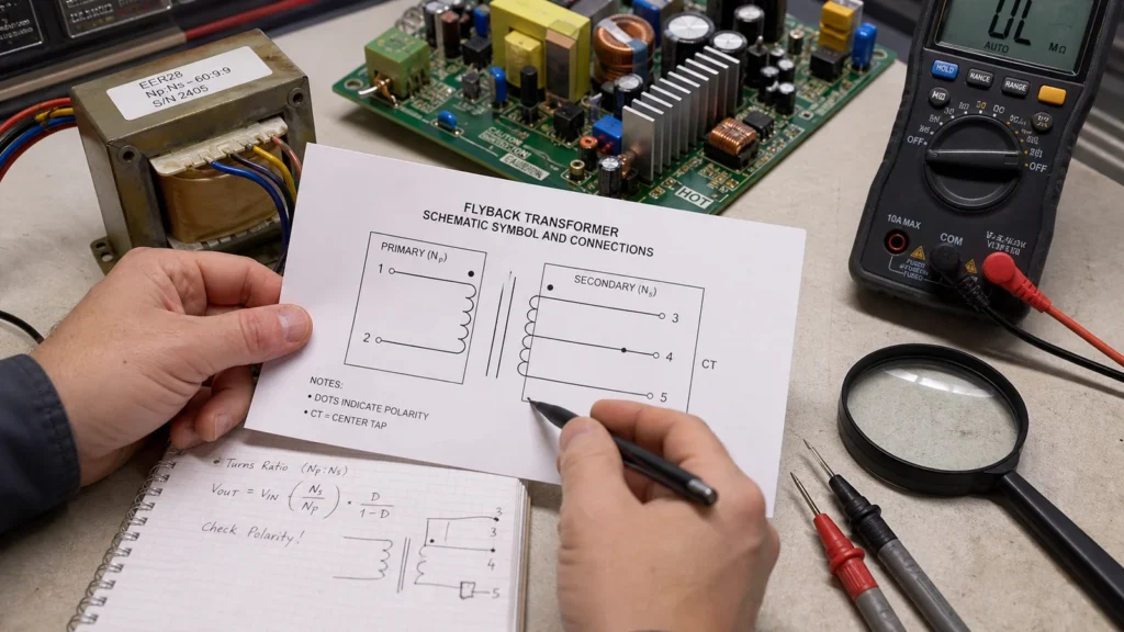
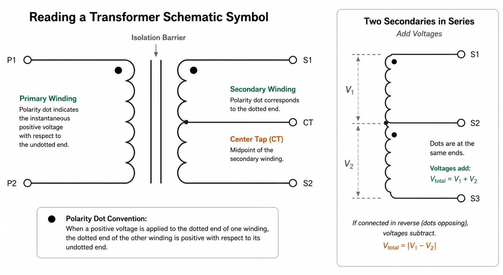
At minimum, the symbol says that two or more windings share magnetic coupling while staying galvanically separate unless the drawing shows an intentional connection. That is the part most readers remember. The part that causes rework is that the symbol also carries clues about polarity, turns ratio, center taps, shielding, and which side of the circuit is expected to stay isolated from everything around it.
On a real board, those clues affect creepage strategy, slot placement, connector labeling, fuse location, probe references during debug, and even which test points can be touched safely during first article inspection. If the schematic symbol is vague, the rest of the design team starts filling in assumptions that may not match the actual transformer part.
Start by separating windings, not by guessing input and output
The first reliable reading step is to identify each winding pair and any explicit tap before deciding which side is primary or secondary. Many schematic libraries draw the windings vertically or horizontally with no universal left-means-primary rule. The net names, surrounding components, and safety references matter more than symbol orientation on the page.
If one winding lands on rectifiers, bulk capacitors, and a low-voltage regulator, that side is functioning as a secondary even if the drafting style makes it look more prominent. If another winding ties into a fuse, EMI filter, common-mode choke, or mains connector, that side deserves the primary-side safety review whether or not the graphic looks familiar.
The dot convention is where wiring mistakes usually begin
When a transformer symbol includes polarity dots, those dots mark the winding ends that rise positive together for the same instantaneous flux direction. That sounds academic until two secondaries are paralleled, a push-pull gate drive transformer is phased incorrectly, or a center-tapped winding is connected in a way that cancels rather than adds voltage.
In bench work, wrong phasing often shows up as an unexpected low output, overheating under light load, a rectifier that sees the wrong stress pattern, or a feedback circuit that behaves backward. On the PCB side, a mislabeled dot can send the layout team toward an apparently neat routing arrangement that later has to be cut and reworked with jumper wires. That is why the dot convention should be checked before symbol capture is signed off, not after the transformer footprint and connector pinout are already frozen.
Center taps, electrostatic shields, and extra windings change the reading
A plain two-winding symbol is only the easy case. Many practical transformer schematics add one or more details that change the interpretation immediately:
- A center tap means the winding is intended to be used as two sections with a defined midpoint, often for full-wave rectification or split rails.
- An electrostatic shield winding, usually tied to chassis or protective earth through a defined path, is about noise control rather than power transfer.
- An auxiliary winding may power startup logic, bias a controller, or provide feedback sense information.
- Multiple secondaries can be isolated from each other, series-connected, or paralleled, but only if the phasing and current-sharing assumptions are correct.
These details matter during DFM review because they affect pin mapping, insulation spacing, and connector documentation. A center tap that is obvious to the power designer can be surprisingly easy to lose in harness documentation or test-fixture labeling if the symbol and net names are not explicit.
How to tell whether the symbol supports isolation or just signal coupling
Not every transformer symbol in a PCB design is about mains isolation. Some are pulse transformers, LAN magnetics, current-sense transformers, gate-drive transformers, or audio coupling parts. The symbol may look broadly similar, but the design consequences are different. A mains transformer or offline flyback transformer forces you to think about reinforced insulation, clearance, and safe probing. A small signal transformer pushes you to think about bandwidth, leakage inductance, common-mode noise, and termination.
The safest reading habit is to ask what job this transformer performs in the surrounding circuit before assigning rules from a different transformer class. Applying mains-layout instincts to Ethernet magnetics wastes board area. Treating an isolated power transformer like a generic coupled inductor can create a safety escape.
A practical review workflow before layout and sourcing
If the transformer symbol is going into a fresh design or a library migration, review it with the surrounding implementation rather than as a standalone drawing object. A practical workflow is:
- Match every winding in the symbol to the exact manufacturer pinout and datasheet naming.
- Confirm the polarity dots or equivalent phasing notes before any parallel or series winding connection is approved.
- Check whether the symbol needs explicit labels for center taps, shields, thermal fuses, or split bobbin construction assumptions.
- Verify the intended isolation boundary and make sure the PCB placement, slotting, and creepage strategy are compatible with it.
- Review how assembly, ICT, and service teams will identify primary-side versus secondary-side test access once the board is populated.
This is also the point where schematic clarity protects purchasing and repair work. If an approved alternate transformer uses a different pin order or combines auxiliary and secondary windings differently, the symbol alone can stop being trustworthy unless the BOM and symbol metadata are kept aligned. That handoff discipline belongs with broader PCB schematic design practice, not as an afterthought once the symbol library is already released.
What the symbol does not tell you unless the design team adds context
A transformer schematic symbol does not tell you copper loss, leakage inductance, saturation current, hipot rating, winding resistance, or which pins are easiest to route without violating creepage. Those are part selection and layout questions, not symbol questions. Problems begin when teams read more certainty into the symbol than it actually contains.
For example, a symbol may show two secondaries that appear interchangeable, while the actual part assigns different current ratings to each section. A repair technician may assume any pair can be joined in series because the drawing is sparse, yet the production notes may rely on one winding for housekeeping power and the other for the load path. A clean schematic symbol is useful only when the supporting notes, BOM, and datasheet reference close those gaps.
Where transformer symbol mistakes show up during debug
Debug symptoms from a misread transformer symbol are often indirect. The transformer may not be the first thing that appears broken. Instead, teams see odd startup voltage, an unexpectedly hot rectifier, wrong gate-drive polarity, unstable feedback, or a secondary output that only fails under load. In lower-power signal circuits, the symptom may be poor waveform amplitude, phase inversion, or noise coupling that looks like a grounding problem. If the part itself is still being chosen, the symbol review should happen alongside PCB transformer selection so the drawing does not drift away from the approved winding arrangement.
That is why a good symbol review belongs alongside how to read electrical schematics in context, not as an isolated library cleanup task. When the symbol is checked against the real transformer job, later failure analysis becomes faster and less dependent on guesswork at the bench.
How this article differs from generic symbol glossaries
Most transformer symbol explanations stop at “these are windings and these are dots.” That is enough for a beginner quiz, but it does not help much when the board has to pass safety review, survive sourcing substitutions, or support a field repair. The better question is whether the symbol communicates enough for the next engineer to make the correct decision without re-deriving the transformer behavior from scratch.
If the answer is no, improve the symbol package. Add winding labels, phasing notes, net intent, or a nearby table tied to the manufacturer pin numbers. That small documentation step usually costs less than one re-spin caused by a swapped winding or an isolation misunderstanding.
Conclusion
A transformer schematic symbol is only useful when it preserves the electrical meaning that layout, assembly, test, and repair teams need. Read the windings first, confirm the dot convention, treat taps and shields as design constraints rather than decoration, and never assume the symbol alone explains the transformer’s real-world role. When that discipline is applied early, the symbol becomes a reliable handoff tool instead of a quiet source of polarity and isolation mistakes.
FAQ
What do the dots mean on a transformer schematic symbol?
The dots mark winding ends that share the same instantaneous polarity. If current or voltage phasing matters, such as when windings are placed in series, paralleled, or used in push-pull drive circuits, the dots tell you which ends rise together.
Does the left winding always mean the primary side of the transformer?
No. Schematic orientation is not a reliable rule by itself. You should identify the primary and secondary from net names, safety context, surrounding circuitry, and the actual transformer pinout or datasheet.
Why is a center tap important on a transformer symbol?
A center tap changes how the winding is intended to be rectified, referenced, or split into two sections. Missing that detail can lead to wrong wiring, incorrect voltage expectations, or a rectifier arrangement that never works as intended.
Can two transformer secondaries be connected in parallel just because the symbol looks symmetrical?
Not safely by appearance alone. You still need matching winding ratings and correct phasing. If the dots or winding data do not support parallel use, the connection can circulate current, overheat the transformer, or collapse the expected output.