A motor schematic symbol looks harmless until someone assumes it tells more than it really does. In practice, the trouble starts when a maintenance print uses one generic motor mark for several different loads, a design library hides whether the motor is single-phase, three-phase, brushed DC, or reversible, or a repair technician has to trace an interlock chain from a crowded control drawing. The symbol is only the entry point. The real job is understanding what kind of motor the circuit is trying to start, protect, reverse, or regulate.
This guide explains how to read a motor schematic symbol without confusing the symbol itself with the power path, control method, or failure mode around it.
What a motor schematic symbol actually tells you
At the most basic level, a motor schematic symbol tells you that electrical energy is being turned into rotary or linear motion somewhere in the circuit. That sounds obvious, but the practical value is in what the symbol does not settle by itself. A circle with an M, a stylized winding mark, or a standards-based machine symbol may confirm the presence of a motor, yet it does not automatically tell you operating voltage, phase count, starting method, direction control, duty cycle, or whether the drawing is showing the power motor itself or only the controlled load in a larger system.
That distinction matters on real equipment. A PCB controlling a fan motor, pump motor, spindle, conveyor, or actuator can fail for very different reasons even when the schematic uses a familiar motor icon. If you read the symbol in isolation, you can misdiagnose the surrounding relays, drivers, overload path, or feedback wiring.
Start with the surrounding circuit, not the icon
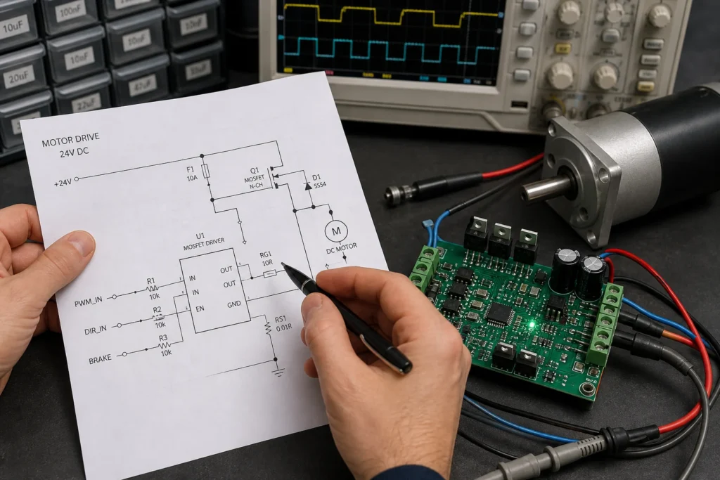
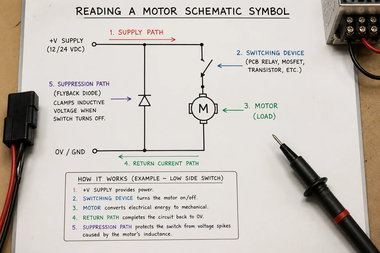
The safest reading habit is to identify how the motor is connected before you try to classify the symbol style. Look at what feeds it, what switches it, and what protects it. A motor tied directly to line power through a contactor and overload block belongs to a different troubleshooting path than a small DC motor driven by a MOSFET bridge on a control board. The schematic symbol may look equally simple in both cases, but the engineering consequences are not similar.
If the motor sits next to a triac, SCR, relay contacts, or VFD output, the drawing is likely part of a control or power-switching system. If it sits beside Hall sensors, encoder lines, current-sense resistors, or a gate-driver IC, you are probably dealing with speed regulation, commutation, or closed-loop control. Reading the symbol this way keeps the schematic connected to how the machine really behaves.
Common motor symbol variations and what they usually imply
Motor symbols vary by drafting standard, industry, and tool library, but a few patterns are common enough to guide your first interpretation:
- A plain circle with M often indicates a generic motor load where the detailed type is defined elsewhere in notes or wiring data.
- A symbol labeled DC, AC, 1~, or 3~ is already giving phase or supply context and should change how you read the upstream switching and protection.
- A reversible motor drawing may show direction contacts, H-bridge behavior, or paired contactors that swap polarity or phase order.
- A stepper or servo system may use a motor mark plus separate winding, driver, or feedback labeling because the symbol alone is not enough to describe the control method.
Even when the symbol variant is recognizable, do not assume the library is perfect. In field drawings and inherited CAD libraries, the wrong symbol is often copied forward because it was “close enough” for a previous revision. That is why a motor symbol should always be checked against the BOM, terminal naming, and control intent.
Why control and protection details matter more than symbol style
Engineers rarely get into trouble because they forgot that a circle marked M means motor. They get into trouble because they miss the protection and control assumptions tied to that motor. A fan motor with a stalled rotor can overheat a driver stage. A reversing contactor without proper interlock logic can short phases. A brushed DC motor can inject enough switching noise to upset nearby logic if the suppression network is missing or degraded. None of those risks are visible from the motor icon alone.
For PCB-related work, this is where the schematic and the board implementation have to stay aligned. A motor output that looks minor on the schematic may require wider copper, better current return control, snubbing, isolation spacing, or connector derating on the actual board. If the motor load is inductive and the schematic fails to show the suppression path clearly, assembly and repair teams can misread a real fault as a random driver failure.
Reading a motor symbol in control schematics versus PCB schematics
Motor symbols appear in at least two very different documentation contexts. In an industrial control schematic, the motor symbol may represent the final machine load while most of the drawing is really about contactors, overloads, permissives, and safety interlocks. In a PCB schematic, the symbol is more likely tied to driver electronics, current sensing, connectors, and firmware-controlled logic. The reading strategy changes with the context.
On control prints, ask what enables the motor, what stops it, and what trips it. On PCB schematics, ask what device switches the motor current, how back-EMF is handled, and whether the control board expects startup surge, braking energy, or fault feedback. The same symbol can sit in either context, but the debug path is completely different.
A practical review checklist before layout, release, or repair
If you need to verify a motor symbol before release or use it to troubleshoot a board, walk through these checks in order:
- Confirm the motor type from labels, part data, or system notes instead of relying on the symbol graphic alone.
- Trace the full power path from supply to switching element to motor return, including fuses, overloads, shunts, and suppression parts.
- Check whether direction control, braking, soft start, or current limiting is implied by surrounding circuitry.
- Verify that connector names, terminal numbers, and PCB net labels match the schematic intent.
- Review failure consequences: stalled load, reversed wiring, missing flyback path, shorted driver, overloaded trace, or poor thermal relief.
This kind of review is where broader PCB schematic design discipline pays off. Clean symbols are useful, but clear net naming, driver annotation, and protection notes are what keep a motor circuit understandable when the board comes back from assembly or lands on a repair bench months later.
Where motor symbol misunderstandings show up during troubleshooting
When a motor-related circuit fails, the symbol is often blamed because it seems too generic. In reality, the fault usually appears one layer deeper. A technician may find a burned MOSFET, welded relay contacts, a nuisance fuse trip, unstable PWM output, or a board that resets whenever the motor starts. Those symptoms point to inrush, inductive kick, grounding, commutation noise, or mechanical overload, not to the symbol itself. But if the schematic uses a vague motor mark with weak labeling, it becomes harder to trace those causes quickly.
That is especially true when the board combines logic and power on the same assembly. Motor return current can contaminate measurement references, heat can drift current-sense readings, and connector wear can mimic driver faults. A better schematic makes those realities easier to spot early.
How this article differs from generic symbol lists
Many symbol libraries and classroom references show a motor icon and stop there. That is fine for memorization, but it is not enough for layout review, DFM, troubleshooting, or service documentation. The more useful question is not “what shape means motor?” It is “what is this motor circuit expected to do, and what board-level or control-level risks sit around it?”
If the symbol package does not answer that question cleanly, improve the documentation. Add phase notes, driver references, terminal labels, direction logic, or protection annotations. A small clarification in the schematic usually saves more time than a polished library symbol with missing context.
Conclusion
A motor schematic symbol is only the start of the story. Read it with the power path, control method, protection strategy, and real load behavior around it. When you do that, the symbol becomes a useful handoff point for design, assembly, and repair instead of a vague icon that hides current, thermal, and switching risks.
Does a motor schematic symbol tell me whether the motor is AC or DC?
Not always. Some schematics use labels or standard-specific variants that identify AC, DC, single-phase, or three-phase operation, but many generic motor symbols do not. You need to read the surrounding supply, switching, and notes to confirm the motor type.
Why is a generic motor symbol not enough for troubleshooting?
Because most motor failures are tied to the surrounding circuit rather than the icon itself. Protection parts, driver stages, overload devices, inrush behavior, flyback paths, and control logic determine how the motor circuit actually behaves and fails.
What should I check first when reading a motor symbol on a PCB-related schematic?
Start by tracing the motor power path, switching device, suppression network, and return current path. That shows whether the board is switching the motor directly, reversing it, sensing its current, or only commanding an external driver.
Can the same motor symbol appear in both industrial control drawings and PCB schematics?
Yes. The same or similar symbol can represent a final machine load in a control drawing or a board-driven motor in an electronics schematic. The symbol may look similar, but the interpretation changes based on the surrounding circuit and documentation context.