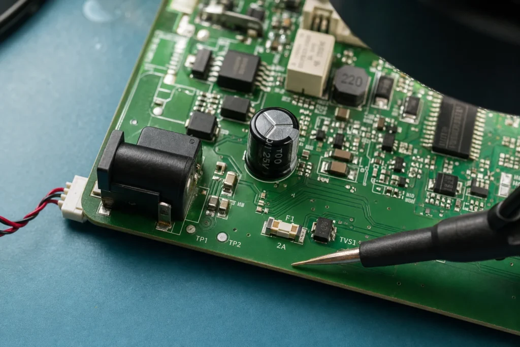
An SMT fuse is easy to underestimate because it looks like one more small rectangular part near the power entry. On a finished board, though, that part is often the last cheap component standing between a wiring mistake, a stalled motor, a shorted regulator, or a damaged connector and a much more expensive repair. If the fuse choice is lazy, it will either nuisance-trip during normal startup or fail to interrupt the real fault energy when the board needs protection most.
That is why an SMT fuse should be selected as a board-level protection device, not as a catalog checkbox. Current rating matters, but so do interrupt rating, I2t, package heat flow, copper area, probe access, and whether the board can actually be serviced after the fuse opens. If you already read fuse symbols in schematics, the next step is turning that symbol into a part and layout choice that still makes sense after assembly, test, and field repair.
What an SMT fuse actually protects on a PCB
A surface-mount fuse is usually placed where the board first becomes vulnerable to overcurrent. That may be the main DC input, a battery branch, a motor or fan rail, an LED power stage, or a subsystem that can fail short and pull down the rest of the design. In low-power boards it is sometimes there to protect the cable, connector, and copper before the ICs are damaged. In industrial or automotive-adjacent work it may also be there to limit downstream damage long enough for a higher-level protection device to react.
The practical question is whether the circuit needs a fuse, which fault the design is trying to contain, and how much energy the board can dump into that fault before something else is destroyed. A USB-powered sensor board, a 24 V control board, and a battery-fed motor controller can all use an SMT fuse, but the correct part class is different because their fault sources and surge behavior are different.
Start with the fault path, not the catalog page
Many selection mistakes start by choosing the current rating first and stopping there. A better workflow is to map the fault path. Identify the source impedance, maximum available current, upstream supply behavior, cable length, connector rating, and which components are most likely to fail short. Then decide whether the fuse is meant to protect the board trace, the load branch, the supply interface, or all three only under a limited set of conditions.
For example, a board powered from a current-limited lab supply may survive a dead short with a small chip fuse that would be useless on a field-installed unit fed from a 24 V DIN rail supply or a high-current battery pack. The same nominal 2 A fuse can behave very differently depending on the source energy behind it. This is also where resettable polymer devices and one-time fuses stop being interchangeable. If the fault must open decisively and stay open until inspection, a traditional fuse often makes more sense than a resettable part that keeps heating and recovering.
Ratings that matter more than the printed current value
Interrupt rating must match the real source
The interrupt rating tells you how much fault current the fuse can safely break. This is where designers get surprised. A fuse that works well on a lightly limited adapter may not be acceptable on a low-impedance DC bus or battery-backed rail. If the available short-circuit current is higher than the fuse interrupt rating, the fuse can arc, char the body, or fail to clear cleanly. That turns the protection device itself into part of the failure.
I2t and startup surge decide whether the fuse is usable
Input capacitors, DC motors, heaters, LED drivers, and some switching regulators create short inrush events that look nothing like steady-state load current. A fuse that is sized too tightly may pass bench bring-up but trip during cold start, brownout recovery, or repetitive load pulsing. Compare the fuse I2t and time-current behavior against the expected surge energy, not just the nominal operating current. If the design depends on a bulk capacitor bank, include the worst-case startup condition after the supply has fully discharged.
Voltage rating, agency approvals, and environment still matter
An SMT fuse on a 48 V telecom rail, a 24 V industrial board, and a 5 V USB device may look mechanically similar, but the voltage rating and safety context are not. If the product enters an approval workflow, the fuse family and its recognition status can affect documentation and replacement rules. Even when formal certification is not the main driver, ambient temperature, sealed enclosures, and poor airflow can shift nuisance-trip behavior enough that a bench-qualified part no longer behaves the same in the field.
Package and layout choices change reliability more than many teams expect
This is where an SMT fuse becomes a PCB problem rather than only a BOM problem. The land pattern, surrounding copper, and placement near heat sources all influence operating temperature and inspection access. If the fuse sits beside a hot linear regulator, MOSFET, or power resistor, the board may preheat the fuse and shrink margin. A package that looks electrically correct can become unreliable because the local thermal map is wrong.
Package size also changes serviceability. Tiny chip fuses save area, but they are harder to probe, harder to replace without disturbing adjacent parts, and easier to misdiagnose when conformal coating or under-filled nearby components block access. The same thinking you would apply to broader surface-mount package tradeoffs applies here: choose the smallest package that still leaves enough room for inspection, rework, and safe soldering margins.
Place the fuse early in the protected path, keep the copper path obvious, and avoid routing critical alternate current paths around it that defeat the protection intent. If the board has test points, add them where continuity and voltage-drop checks can be made without scraping solder mask or probing directly on the fuse body. That small DFT choice often saves more troubleshooting time than the fuse itself costs.
When an SMT fuse is the right answer and when it is not
An SMT fuse is usually a good fit when board area matters, assembly is automated, and the fault you need to isolate is local to the PCB. It is common on compact control boards, LED power sections, embedded products with exposed power connectors, and branch protection inside larger electronic assemblies.
It is a weaker fit when replacement access is poor, field technicians are expected to service the unit without microscope-grade tools, or the source energy is high enough that a panel fuse, cartridge fuse, or coordinated upstream protection scheme is safer. In some products, the right answer is not a smaller SMT fuse but a redesign of the fault domain so that the board never has to interrupt the full available current alone.
How to troubleshoot an SMT fuse on an assembled board
Treat an open fuse as evidence, not as the root cause. First isolate whether the board failed because the fuse did its job or because the fuse choice was wrong. Check continuity with power removed, then measure the voltage on both sides of the fuse during a controlled power-up if the system can be powered safely. Using the right multimeter modes during board troubleshooting matters here, especially when low-resistance paths or inrush behavior can mislead a quick reading.
If the fuse is open, inspect what it was protecting. Look for shorted input capacitors, damaged TVS diodes, reversed-polarity events, pinched harnesses, cracked connectors, or downstream regulators that failed short. Also inspect the solder joints and pad condition before replacing it. A poorly wetted joint or overheated pad can create intermittent heating that looks like fuse fatigue. When you do replace the part, bring the board back on a current-limited supply first and confirm the fault current does not immediately climb again.
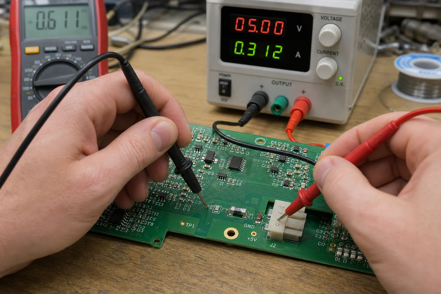
On higher-risk boards, record the measured startup current and the likely fault energy so the next revision can be improved instead of only repaired. That feedback loop is where a fuse selection article becomes a design-quality article: the best protection part is the one that fits the board, the source, the assembly process, and the repair reality at the same time.
What is the difference between an SMT fuse and a resettable fuse?
An SMT fuse usually opens permanently and forces inspection before power is restored, which is useful when a real fault must be contained decisively. A resettable device can be useful for limited overcurrent events, but it may stay warm, recover unpredictably, and hide the original failure mode if the board is repeatedly powered without diagnosis.
Where should an SMT fuse be placed on a PCB?
Place it early in the branch you want to protect, normally close to the power entry or ahead of the vulnerable subsystem. Keep the current path obvious, avoid bypass current routes around the fuse, and leave enough room for probing, inspection, and safe rework.
Why does an SMT fuse trip even when the board current looks normal?
The steady-state current may be normal while startup surge, capacitor charging, motor stall, or local heating pushes the fuse outside its time-current margin. Check inrush energy, nearby heat sources, copper spreading, and whether the installed fuse family matches the actual source impedance.
Can an SMT fuse protect a board powered from a high-current battery?
Only if its interrupt rating and fault-clearing behavior are appropriate for the available short-circuit current. In battery-fed or low-impedance systems, a small chip fuse may be inadequate by itself, so coordinated upstream protection or a different fuse format may be necessary.