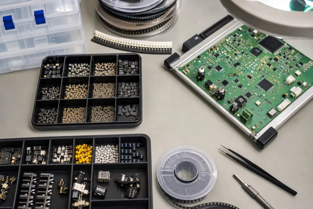
Surface mount components are the parts mounted directly onto copper pads instead of being pushed through drilled holes. That definition is correct, but it is too thin to help with a real PCB release. The moment a board moves from schematic to assembly, the useful questions become more practical: which package families are on the board, which ones are sensitive to paste volume or skew, which ones hide solder joints from inspection, and which ones make field rework expensive.
That is why engineers who already understand the acronym still spend time reviewing package choice. A resistor array, a QFN controller, a bottom-terminated power device, and a board-edge connector can all be called surface mount components, yet they place very different demands on land pattern control, thermal balance, AOI visibility, and hand-repair access. If you are documenting surface mount device package choices, the package body matters almost as much as the schematic function.
What surface mount components really include on a PCBA
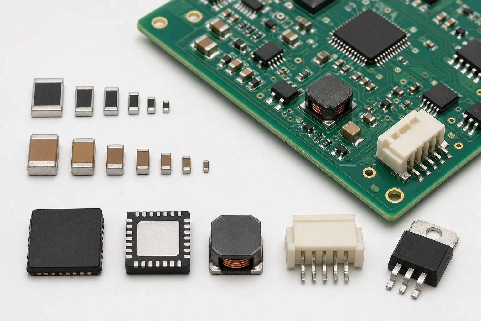
On a finished assembly, surface mount components usually fall into a few repeated families. Passives such as resistors, capacitors, ferrite beads, and inductors dominate the part count. Logic and analog ICs bring the dense pitch, thermal pads, and moisture-sensitivity issues. Power parts add heavier copper demand, larger thermal gradients, and sometimes awkward lead shapes. Connectors, shields, crystals, sensors, LEDs, and protection devices round out the places where placement force, solder joint geometry, or board flex can become the real problem.
The mistake is to treat all of those families as one generic SMT bucket. A 0603 resistor is mostly a placement and tombstoning discussion. A fine-pitch QFP is a bridge-risk and coplanarity discussion. A QFN with an exposed pad brings stencil aperture design, voiding control, and rework difficulty into the conversation. A large shield can shadow nearby parts in reflow and inspection. Saying the board uses SMT components is only the starting point.
Passives do not stay simple when density rises
Small passives look easy until density, panel handling, and thermal imbalance stack up. The jump from 0805 to 0402 or 0201 is not just a space-saving move. It changes feeder setup sensitivity, paste volume tolerance, and the amount of solder imbalance needed to create tombstoning. Dense passive banks also make microscope access and post-reflow rework slower, especially when the board packs parts close to tall connectors or heat sinks.
IC packages decide how visible your solder joints are
Leadless packages can improve electrical and thermal performance, but they remove visual comfort. QFNs and bottom-terminated regulators hide the joints that technicians would otherwise inspect quickly under magnification. BGAs raise the same issue at a higher scale: routing freedom increases, but X-ray dependence, warpage sensitivity, and profile discipline become more important. If the board is expected to be debugged in low volume, package convenience for assembly may need to be weighed against serviceability.
Why package choice changes assembly risk more than the part description
The component name in the BOM rarely tells the full manufacturing story. A buck regulator may exist in a forgiving gull-wing package or in a thermally efficient QFN that demands better stencil tuning and pad design. An MCU in TQFP gives visible solder fillets and easier rework, while the same device family in BGA may save routing layers but raise inspection cost. That is why experienced teams review package risk alongside electrical fit instead of leaving it as a late purchasing or assembly surprise.
This is also where surface-mount layout decisions start to matter. Package pitch influences whether solder mask dams remain manufacturable. Body size influences courtyard spacing and tool access. Thermal-pad geometry influences voiding and planarity. Tall neighboring parts influence nozzle access and AOI line of sight. In other words, package choice is not a library decision living in isolation. It changes the board around it.
Checks worth doing before releasing SMT components to assembly
A useful pre-release review goes beyond “the part fits.” Confirm polarity marks are obvious in the silkscreen or assembly drawing, especially for diodes, electrolytics, LEDs, and polarized IC orientations. Check whether the package needs a thermal pad windowing strategy instead of one large paste opening. Review moisture-sensitive devices so baking, floor life, or dry-pack requirements do not become last-minute production noise. If the design includes bottom-terminated parts, decide early whether AOI is enough or whether X-ray sampling will be needed.
It also helps to review the board from a repair perspective. Can hot air reach the part without cooking nearby plastics? Is there enough keep-out around large ground-connected packages for reliable rework? Will a failed connector or shield force destructive removal because other parts are trapped too close? These are the kinds of details that strong SMT assembly process control catches before the first build turns into a lesson on avoidable rework labor.
When surface mount components are the wrong answer
Surface mount wins on density and automation, but it is not automatically the best answer for every location. High insertion force, repeated cable stress, large mechanical shock, or frequent field replacement can still justify through-hole hardware, selective soldering, or mixed-technology assembly. The right question is not whether SMT is modern enough. The right question is whether the package survives the thermal, mechanical, and service conditions the product will actually see.
That is why a balanced design can mix SMT passives, fine-pitch controllers, and through-hole support hardware without contradiction. Good engineering treats component style as a reliability choice, not a fashion choice. The board should use surface mount components where they help density, routing, and automated build consistency, and it should avoid them where joint visibility or mechanical retention matter more.
Conclusion
Surface mount components are not just “small parts on the board.” They are the package-level decisions that shape placement stability, reflow behavior, inspection reach, and service difficulty. Once you group them by the risks they introduce instead of by a simple acronym, the review process gets sharper and the first build usually gets easier.
FAQ
What is the difference between a surface mount component and a through-hole component?
A surface mount component solders directly to PCB pads, while a through-hole component uses leads or pins inserted through drilled holes. SMT usually saves space and supports automation, but through-hole parts can still be better for mechanical strength or repeated service.
Which surface mount components are hardest to assemble reliably?
Bottom-terminated packages, fine-pitch leaded ICs, BGAs, large thermal-pad devices, and very small passives tend to create the most assembly sensitivity because they raise the need for precise paste control, profile tuning, inspection access, or careful rework planning.
Are SMT components always better for modern PCB design?
No. They are usually better for density and automated placement, but connectors, high-stress hardware, or parts that must be replaced often may still be better handled with through-hole or mixed-technology design choices.
Why does the package matter if two parts have the same electrical function?
The package changes land pattern geometry, solder joint visibility, thermal behavior, pick-and-place stability, and repair access. Two electrically similar parts can create very different manufacturing risk if their packages are different.