When someone searches for the fuse schematic symbol, they usually do not need a long history lesson about fuses. They are trying to answer a practical question fast: Is this symbol a fuse, what kind of protection does it imply, and what should I check next on the board or wiring diagram? That is the right way to approach it.
In real circuit work, the fuse symbol matters because it tells you where overcurrent protection is intentionally placed in the design. On a PCB, wiring harness diagram, appliance control board, or power entry section, that symbol is often one of the first clues for how the designer expected the product to fail safely. If you read it correctly, you can troubleshoot faster, choose a more appropriate replacement part, and avoid dangerous assumptions about what is upstream and downstream of the protected node.

What the fuse schematic symbol tells you at a glance
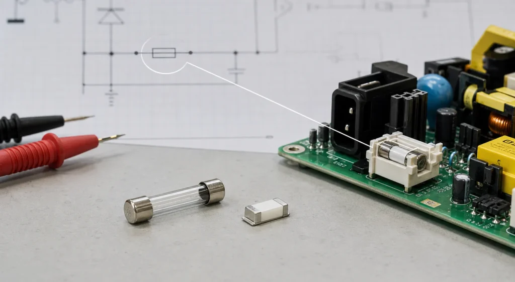
At the most basic level, the fuse symbol marks a sacrificial overcurrent protection device placed in series with the circuit path. The design intent is simple: under fault current, the fuse should open before traces, connectors, wiring, or semiconductors suffer more serious damage.
The important engineering detail is that the symbol usually tells you function first, not the full replacement specification. A drawing may clearly show that a fuse exists, while the actual current rating, interrupt rating, time-delay class, package style, and agency approvals are stored elsewhere in the BOM, notes, silkscreen, or service documentation. Engineers and technicians get into trouble when they treat the graphic symbol as a complete part description. It is not.
A fuse reference designator is commonly tied to the letter F, such as F1 or F101. That is a strong hint that you are looking at a protective fuse location rather than a resistor, jumper, or ferrite bead. If the drawing is crowded or low resolution, the designator is often what resolves ambiguity fastest.
Common fuse symbol variants you may see
The exact artwork is not identical on every drawing. The main reason is that schematics are influenced by drafting standards, EDA library choices, industry habits, and whether the diagram is electronics-oriented or industrial-electrical in style.
In practice, you will usually see one of these situations:
1. A generic fuse symbol
This is the simplest representation and only tells you that a fuse is present in series with the line. It is common in electronics schematics, service manuals, and quick block-level diagrams where the author wants to show protection intent without clutter.
2. A symbol plus a text label
Many professional schematics intentionally keep the symbol generic and attach the real selection data in text nearby, such as 2 A slow-blow, 500 mA fast-acting, 125 V, or a part number. This is often the most useful approach because it avoids symbol-library debates while preserving the information needed for manufacturing or repair.
3. A resettable fuse or PTC-style protector
A resettable polymer fuse may be drawn differently from a one-time fuse, or it may be labeled explicitly as PTC, polyfuse, or resettable fuse. This distinction matters. If the part can self-reset after the fault is removed, your troubleshooting logic changes. A blown one-time fuse and a tripped resettable protector do not behave the same in the field.
4. Industrial-electrical protection assemblies
In machine schematics and panel drawings, you may also see fused disconnects, fuse switches, or multi-pole protective assemblies. The symbol no longer represents a tiny PCB part alone. It can indicate a fuse that is functionally tied to a switch, isolator, or higher-level protection assembly.
For that reason, do not memorize only one icon shape and assume every other drawing is wrong. A better habit is to read the symbol together with the reference designator, surrounding connections, and annotation style.
How to tell a fuse from similar-looking symbols
Fuse vs. circuit breaker
A fuse is normally intended to open irreversibly under fault conditions and then be replaced. A circuit breaker is meant to trip and be reset, either manually or automatically depending on the design. In industrial or electrical distribution drawings, the two symbols may live close to each other, so the surrounding labeling matters. If the designator starts with CB, Q, or uses breaker terminology, do not assume it is a fuse even if the line protection role looks similar.
Fuse vs. resistor
On poor photocopies or old PDFs, a simple fuse symbol can be confused with a resistor symbol, especially if the symbol libraries follow different regional conventions. The easiest check is the designator. R indicates resistor, F indicates fuse. The second check is placement. A fuse is often near power entry, battery input, external connector rails, motor supply branches, or hazardous-energy sections where fault isolation matters.
Fuse vs. ferrite bead or jumper
PCB schematics sometimes place ferrite beads, zero-ohm links, and fuses in similar series positions. If you only look at the line interruption, they may all seem alike. Again, the reference designator solves most confusion: FB for ferrite bead, R0 or a jumper label for a zero-ohm link, and F for fuse. The functional meaning is completely different, especially when you are deciding whether a missing part should be replaced with a protective element or a low-impedance connection.
One-time fuse vs. resettable fuse
This distinction matters in consumer electronics and USB-powered products. A board that repeatedly “comes back to life” after cooling may be using resettable protection rather than a cartridge or chip fuse. The schematic symbol may hint at that, but the label usually confirms it.
What the symbol means in PCB design and repair work
A fuse symbol is more than an icon for beginners. It tells experienced engineers where the designer expected the fault boundary to be.
On a PCB, a fuse at the input side often means the board designer wanted to protect the entire downstream assembly from reverse events, wiring mistakes, adapter faults, or catastrophic load shorts. A smaller branch fuse may indicate that a motor driver, heater, LED rail, or external connector is considered the higher-risk section.
That matters during repair. If F1 is open, replacing it blindly is not a diagnosis. It is only the beginning of the diagnosis. The next step is to ask why that protective element opened. Check the downstream rail resistance, look for shorted power semiconductors, inspect electrolytics and TVS parts, and verify whether the board uses inrush-limiting or soft-start elements that could change startup behavior.
This is also where good schematic-reading habits help. If you already use a structured reading method like the one described in ReversePCB’s guide on how to read electrical schematics, the fuse symbol becomes part of the power-path story rather than a disconnected graphic. And if you need to decode a crowded service print, the broader naming context in 140 commonly used PCB markings can help confirm what the designator means.
Common mistakes engineers and technicians make
Assuming the symbol defines the exact replacement part
It does not. The symbol shows the presence and role of the fuse. The safe replacement still depends on current rating, voltage rating, interrupt capacity, time-current behavior, package, mounting style, and safety approvals.
Replacing a fuse with wire or a zero-ohm part during testing
That shortcut can destroy the real fault evidence and create a much larger failure. If you need controlled fault finding, use a current-limited bench supply or a proper service method instead of bypassing the protection permanently.
Missing the difference between board-level and system-level protection
A schematic may show a local board fuse while the product also contains a mains fuse, supply-limited adapter, breaker, or battery protection circuit elsewhere. Reading only one sheet can lead to wrong assumptions about what is actually protected.
Ignoring why the fuse is located where it is
Placement is part of the engineering message. A fuse near an external connector suggests protection from field wiring or user-connected loads. A fuse on a DC rail feeding one subsystem may show intentional fault containment for that branch only.
How to draw and document fuse symbols more clearly
If you are creating schematics instead of only reading them, the best practice is to make the symbol easy to recognize and let the documentation carry the precise part choice. Use a consistent library symbol, keep the F reference designator obvious, and add the rating or part note where a technician can see it without opening the BOM.
For branch protection on complex boards, it also helps to place nearby notes that explain whether the device is fast-acting, time-delay, resettable, or intended only for service-level replacement. That saves time later for test engineers, contract manufacturers, and repair teams.
Final takeaway
The fuse schematic symbol tells you that the designer intended a particular current path to be sacrificially protected. That is the core meaning. But the symbol alone does not tell you everything you need to replace or troubleshoot the part safely.
Read the symbol together with the F designator, nearby text, circuit position, and downstream load. Distinguish it from breakers, resistors, ferrite beads, and resettable protectors. Then treat an open fuse as evidence of a fault path, not as the entire fault itself.
If you build that habit, the fuse symbol becomes much more than a memorized icon. It becomes a fast entry point into the circuit’s protection strategy.
Does the fuse schematic symbol tell me the exact replacement fuse?
No. The symbol tells you a fuse is present, but the exact replacement still depends on the rating, speed class, interrupt rating, package, and approvals listed elsewhere in the design documentation.
How can I tell a fuse from a circuit breaker on a schematic?
Check the designator and the surrounding notation. A fuse is usually marked with an F reference such as F1, while breakers often use different symbols and designators such as CB or panel-style protective labeling.
Can a resettable fuse use a different symbol from a one-time fuse?
Yes. Many schematics label resettable protection explicitly as PTC, polyfuse, or resettable fuse, and the symbol may differ from a one-time fuse to show different behavior in service.
What should I check if a fuse marked F1 is open on a PCB?
Do not replace it blindly. Check the downstream rail for shorts, inspect power semiconductors and capacitors, and confirm whether another fault caused the fuse to open before fitting a replacement.