An SMT fuse looks small enough to disappear into the rest of the layout, which is exactly why it gets chosen too late in many designs. Engineers often size the current rating, drop the part near the input path, and move on. That works until inrush current, fault energy, ambient heat, or service access proves that the protection strategy was never fully defined. A surface-mount fuse only does its job when the board, the power source, and the failure mode were considered together.
For PCB assembly teams, an SMT fuse is not just a schematic symbol. It is a current-limiting component with a package, a thermal environment, solder-joint demands, and replacement implications. Those details matter because a fuse that nuisance-trips in production test wastes time, while a fuse that holds too long can let copper, connectors, or downstream ICs absorb the real damage.
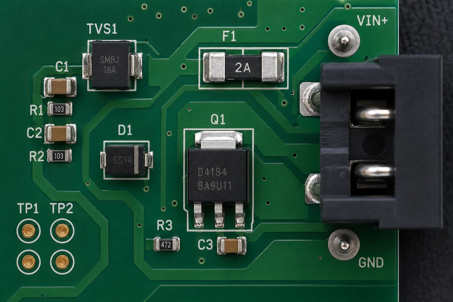
What an SMT fuse actually protects on a board
An SMT fuse is usually there to open the circuit when abnormal current exceeds what the board or downstream circuitry can tolerate. That may sound simple, but the real design question is what you are protecting: the input connector, a battery path, a charging stage, a DC-DC front end, a USB branch, or a sensitive downstream load. If that answer is vague, the fuse choice will also be vague.
The package is only one part of the story. Surface-mount fuses are chosen because they fit automated assembly, reduce manual insertion, and integrate cleanly into dense layouts. But once the fuse is on the board, it behaves like any other component that is sensitive to land pattern, copper heat sinking, reflow exposure, and service access. ReversePCB’s article on surface-mount package selection is relevant here because protection parts are still packages with assembly consequences, not abstract safety checkboxes.
The selection factors that matter more than the headline current rating
Rated current is the first filter, not the final answer. The board’s normal operating current, startup surge, capacitor charging behavior, motor or backlight inrush, and transient fault profile all matter. A fuse that looks correct in steady-state math may trip during every cold start if the inrush envelope was ignored. The opposite mistake is choosing a part with so much time-delay margin that a real short circuit cooks copper or overstresses the connector before the fuse opens.
Voltage rating matters because the fuse has to interrupt the expected fault safely. Interrupt rating matters because not every fault is a soft overload. In battery packs, adapter-fed systems, or industrial inputs, the available fault current can be much more aggressive than hobby-level examples suggest. Engineers also need to think about I2t behavior, because the energy let through during a fault often determines whether downstream silicon survives.
Package size matters for both electrical and service reasons. Very small fuses save space, but they can become awkward to probe, replace, or visually inspect after a field return. If the product is expected to be reworked by hand or repaired in low volume, the smallest package is not automatically the best package.
How layout and assembly can change fuse behavior
Fuse behavior is affected by the copper it sits on. Heavy copper pours and large adjacent planes can pull heat away from the fuse and shift how it responds under overload. Tight placement near hot regulators or enclosed power modules can raise ambient temperature and narrow margin. In other words, the same fuse in two different layouts may not behave exactly the same.
This is also where PCB assembly discipline matters. The land pattern needs to match the manufacturer recommendation, and the paste deposit has to avoid weak joints or excess solder that lifts the body unevenly. If the fuse is placed near board edges, large connectors, or mechanically stressed cables, joint fatigue becomes part of the reliability picture. ReversePCB’s guide to surface-mount layout and rework risk is useful because protection parts often fail from poor context, not only from poor specifications.
When a resettable protector may be better than a one-time fuse
Some boards are better served by a resettable polymer protector than by a one-time fuse, especially when the most common fault is a temporary overload rather than a destructive hard short. That does not make resettable parts automatically superior. Polymer devices have different hold and trip behavior, temperature sensitivity, and post-trip resistance characteristics. If the product cannot tolerate lingering resistance, repeat nuisance trips, or slow reset behavior, a conventional SMT fuse may still be the cleaner solution.
The right choice depends on how the product fails in the real world. A lab bench prototype with occasional cabling mistakes is different from a sealed product that must fail safe and stay isolated after an internal short. Protection strategy should be chosen from the failure mode backward, not from package inventory forward.
Common SMT fuse mistakes in PCB projects
One common mistake is placing the fuse too far downstream, after the vulnerable trace section or connector that needed protection in the first place. Another is copying a fuse value from a reference design without checking how the new board changes startup current, ambient temperature, or branch loading. Teams also get into trouble when they leave no probe access around the fuse, which turns a simple debug check into a board-level disassembly job.
Another subtle mistake is forgetting rework reality. If a fuse is likely to be replaced during failure analysis, the surrounding component spacing should support hot-air access without cooking nearby plastic connectors or disturbing tiny passives. ReversePCB’s article on surface-mount soldering and rework damage is relevant because protection parts are often touched during repair, not only during the first build.
How to validate an SMT fuse choice before release
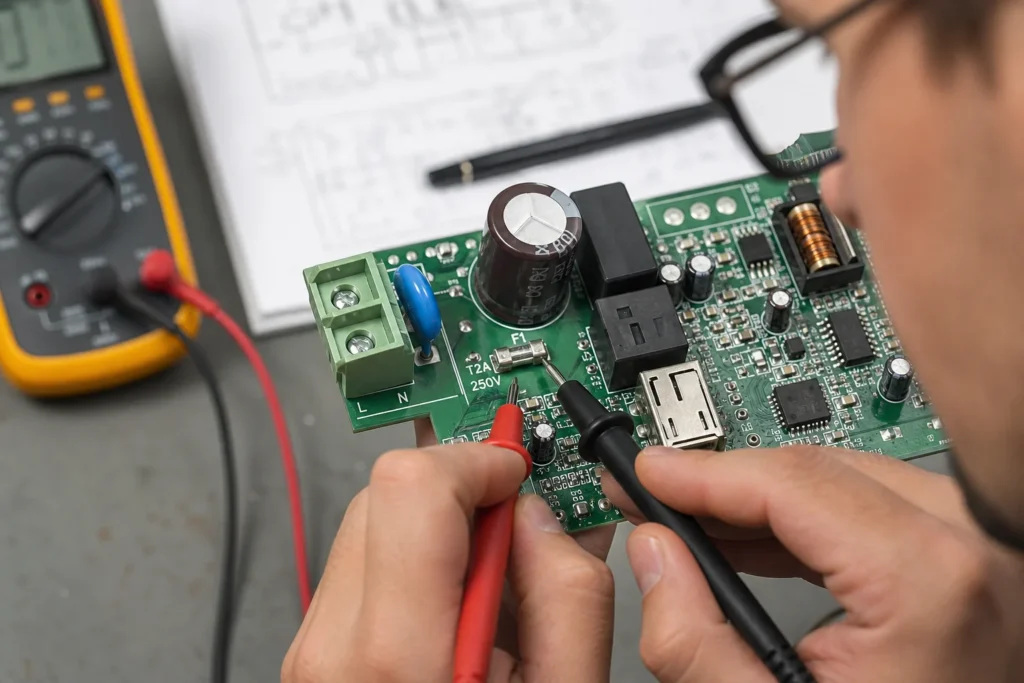
The validation checklist should include more than continuity. Measure normal current at temperature, capture startup surge, test credible overload cases, and confirm that the fault clears before copper, connectors, or downstream semiconductors become the sacrificial path. If the board will be assembled in volume, also confirm that the fuse package survives reflow cleanly and remains inspectable after conformal coating or mechanical enclosure constraints are added.
A good fuse choice is the one that behaves predictably in the board’s real electrical and thermal environment. That is a stronger standard than “the rating looked close enough in the catalog.”
Conclusion
An SMT fuse is a small component with system-level consequences. The right part is chosen by matching normal current, inrush behavior, voltage, available fault energy, layout temperature, and service expectations to the actual protection goal. When those variables are reviewed together, the fuse protects the board. When they are treated as a quick BOM line item, the board ends up protecting the fuse decision instead.
FAQ
What is an SMT fuse used for on a PCB?
An SMT fuse is used to interrupt excessive current on a PCB before traces, connectors, power stages, or downstream components are damaged. It is part of the board-level protection strategy, not just a catalog component.
How do you choose the right current rating for an SMT fuse?
Start with normal operating current, then check startup surge, ambient temperature, expected overloads, and the protection target. A fuse that only matches steady-state current can still nuisance-trip or fail to clear a real fault correctly.
Does PCB layout affect how an SMT fuse behaves?
Yes. Copper area, nearby heat sources, pad design, and physical placement can change thermal conditions and sometimes influence fuse behavior during overload. Layout also affects inspection and replacement access.
When is a resettable protector better than a one-time fuse?
A resettable protector can be better when temporary overloads are common and the product should recover without part replacement. It is not always better, because post-trip resistance, reset timing, and fault-clearing behavior may not fit every design.