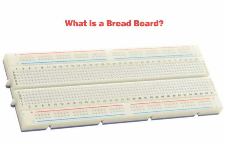
What is a Bread Board?
A breadboard is a device used for prototyping electronic circuits without the need for soldering. It consists of a board with multiple small holes or sockets that allow electronic components to be easily inserted and removed as needed. Breadboards are commonly used for circuit design, testing, and training as they allow for quick and easy modifications to be made without the risk of damaging components. The use of breadboards has become popular due to their convenience, cost-effectiveness, and the ability to reuse components.
Bread Board Structure
The breadboard is typically made of a thermosetting phenol formaldehyde resin with metal strips on the underside. The holes on the board are drilled in such a way that when circuit board components are inserted into them, they make contact with the metal strips, thus achieving conductivity. Usually, every 5 holes are connected by a metal strip. There is a central groove on the board designed for integrated circuit and chip experiments. There are two rows of vertical sockets on either side of the board, also grouped in sets of 5. These sockets are used to provide power to the components on the board.
Terminal Strips
The terminal strip is the most basic structural part of the breadboard, and it looks like a square hole in appearance. If we violently open a breadboard, we will find terminal pieces like the one below, each of which is connected by 5 small clips. And the small chuck can just be stuck in the square grid of the plastic part. In this way, when we insert the jumper wire or the pin of the electronic component into the square grid, it can be clamped by the small clip. Then the breadboard is made of such metal pieces arranged.

DIP Support
Breadboards usually have a long groove in the middle as Dual Inline Package (DIP) support, as shown in the picture below:

The spacing between the jacks near both sides of the groove is generally 7.62mm, which is exactly the same as the component size of the standard DIP pin. After the DIP IC is plugged in, it is often difficult to pull it out by hand due to too many pins. If it is pulled out violently, it is easy to bend the pins, and the groove is just enough for tools such as tweezers to reach down and take out the IC.
Power Rails
As shown in the figure, there are often two rows of jacks on both sides of a standard large breadboard, usually with a “+” for the red line and a “-” for the blue or black line. This is the power channel dedicated to providing the power jack for the entire board.

It should be noted that there is no path between the power channels on both sides. So if you want to have power on both sides, it is best to use jumpers to connect the channels on both sides, as shown in the figure below.

Types of Breadboards
There are three main types of breadboards: the solderless breadboard, the single-sided breadboard, and the combination breadboard.
Solderless breadboard
This type of breadboard does not have a base plate or soldered power sockets. Before use, it needs to be powered by connecting the power poles to the two-sided socket on the breadboard. Components can then be inserted and tested by plugging them into the board. When more than five components or one set of sockets cannot be plugged in, use a breadboard wire to connect multiple sets of sockets.
Single-sided breadboard
This type of breadboard has a base plate and specialized power terminals, and some can even be used for high voltage experiments. It is easy to use: Connect the power directly to the terminal, then plug in the components for testing. When more than five components or one set of sockets cannot be plugged in, use a breadboard wire to connect multiple sets of sockets.
Combination breadboard
This type of breadboard is made by combining multiple solderless breadboards on a baseplate. Two to four solderless breadboards are typically fixed on the baseplate, and their power lines are connected by copper foil. Combination breadboards are versatile and can be used for large-scale experiments, but they are not portable due to their size and weight. They are ideal for laboratory use and electronics enthusiasts.
How to Use a Bread Board?
Here’s how to use a breadboard:
Familiarize yourself with the breadboard
A breadboard is typically made up of rows of holes, with each row connected internally by a strip of metal. The rows are usually labeled with letters and numbers to help you keep track of where you are placing each component.
Select your components
Before you start placing components on the breadboard, you need to decide which components you will be using. It’s a good idea to sketch out your circuit diagram on paper before you start so that you have a clear idea of what you need.
Place the components
Begin by placing the components on the breadboard in the appropriate locations. For example, if you are building an LED circuit, you will need to place the LED in one row and the resistor in another.
Connect the components
Once all of the components are in place, you will need to connect them together using jumper wires. Jumper wires are short lengths of wire with pins on either end that fit into the holes on the breadboard.
Test the circuit
Once the circuit is complete, it’s time to test it. Connect a power source to the circuit and make sure that everything is working as expected.
Technical Application Notes for Bread Board: What is and How to Use it?
These additions address practical search intent while preserving the original page structure and existing ranking content.
- Check the key electrical, mechanical, and environmental assumptions before applying the page guidance to a real design.
- Cross-reference critical values with the latest datasheet, application note, IPC document, or manufacturer capability table.
- During PCB implementation, account for package size, thermal path, signal routing, power distribution, and test access.