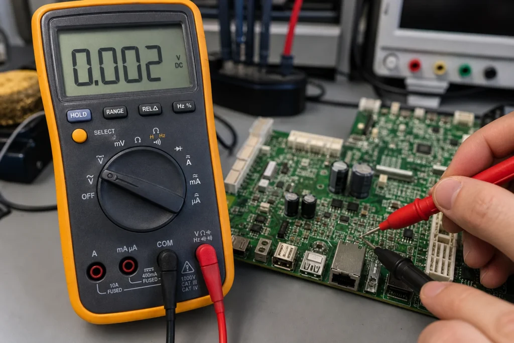
Multimeter symbols look simple until you are probing a real board and the wrong dial position gives you a misleading reading. On a PCB bench, the symbol matters because it changes what the meter is actually injecting, measuring, or filtering. The continuity beep icon is not the same as resistance mode, the diode symbol is not a generic component check, and the AC/DC markings change how the meter interprets a waveform.
This guide explains the multimeter symbols that matter most for electronics troubleshooting, especially when you are checking a PCB, cable harness, connector, fuse path, diode, or power rail. The goal is not to memorize every icon on every meter. It is to know what the common symbols mean, when to use them, and where they can fool you during board-level diagnosis.
Why Multimeter Symbols Matter More on a PCB Than on a Loose Component?
When you test a loose resistor or an unplugged switch, the symbol mostly tells the meter what range to use. On an assembled board, the same symbol affects how the meter behaves inside a network of parallel paths, semiconductor junctions, charged capacitors, protection devices, and power rails that may still hold residual voltage.
Continuity mode looks for very low resistance and often adds an audible beep threshold.
Resistance mode gives a value, but parallel circuits can make a good part look wrong.
Diode mode applies a small test current and reports forward voltage, which is useful for junction checks but not for every in-circuit component.
AC and DC voltage symbols tell the meter how to interpret the waveform, and choosing the wrong one can hide a ripple problem or understate a DC rail fault.
That is why symbol recognition is not just beginner trivia. It directly affects whether your troubleshooting conclusion is trustworthy.
The Multimeter Symbols Engineers Use Most Often
Most board-level troubleshooting comes back to six symbol groups: continuity, resistance, diode, direct current voltage, alternating current voltage, and current measurement. Different meters draw them a little differently, but the underlying functions stay consistent.
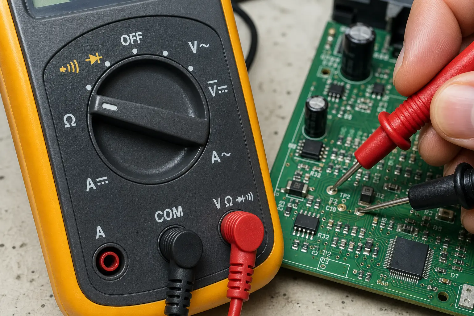
Continuity symbol. Usually a sound-wave icon, a buzzer mark, or continuity combined with the diode position. This is the symbol people look for when they want the meter to beep on a low-resistance path.
Ohms symbol. The Greek omega symbol means resistance measurement. It is better than continuity mode when you care about the actual value instead of a simple pass/fail beep.
Diode symbol. Used to check forward drop across a diode or PN junction. It can also help identify shorted or open semiconductor junctions during fault isolation.
DC symbol. Commonly a straight line over a dashed line. This is the usual setting for most PCB power rails, batteries, and logic supply measurements.
AC symbol. Usually a tilde or wave mark. Use it when you expect alternating voltage or when you are checking ripple or transformer outputs that are not pure DC.
Current symbols. Marked as A, mA, or uA with AC or DC indicators. These settings require the leads to be in the correct current jack, and misuse is one of the fastest ways to blow a meter fuse.
What the Continuity Symbol Actually Means
The multimeter continuity symbol usually shares the dial position with the diode function on compact digital meters. In this mode, the meter is looking for a low-resistance path between the probes and will often beep when the measured resistance falls below a built-in threshold. That threshold is not universal. One meter may beep below roughly 30 ohms, another may wait until the path is much lower.
That detail matters on PCBs. A fuse, trace, connector, or switch path can be electrically valid but still sit near the meter’s threshold because of contact oxidation, long wire length, relay contacts, or current-limited protection elements. In other words, no beep does not always mean no connection, and a beep does not always mean a healthy low-impedance path under load.
If you are checking traces, vias, or connector pins, continuity mode is a fast first pass. If you need to understand how good the path is, switch to resistance mode and interpret the number rather than the sound.
DC and AC Symbols Are Not Interchangeable
The DC symbol on a multimeter is usually shown as one solid horizontal line with a broken or dashed line beneath it. This is the correct setting for batteries, regulator outputs, logic rails, most microcontroller supply pins, and many analog bias points on a PCB.
The AC symbol on a multimeter is usually a wave or tilde. It is for transformer secondaries, mains-derived AC, audio-frequency alternating signals, or ripple checks where the AC component is what matters.
Using the wrong symbol creates bad diagnostics. Measuring a DC rail in AC mode can make a normal 5 V supply look nearly dead. Measuring a noisy DC rail only in DC mode can hide excessive ripple from a failing regulator, bad capacitor, or overloaded switcher. Good troubleshooting often means checking both: DC for nominal rail value, then AC for unwanted ripple riding on top of it.
When Resistance and Diode Symbols Tell You More Than Continuity
Continuity mode is fast, but it is also blunt. If a board fault is subtle, other symbols give better information.
Use resistance mode when you need to compare one rail to ground, confirm whether a jumper or shunt is really near zero ohms, or judge whether contact resistance is too high for a low-level signal path.
Use diode mode when you suspect a reversed diode, a shorted TVS, a damaged transistor junction, or an unexpected semiconductor path between a rail and ground.
Do not trust any in-circuit resistance reading blindly if the node is tied to capacitors, parallel resistors, IC pins, or ESD structures. Lift one side or isolate the circuit if the reading drives a repair decision.
That is also why a general circuit board testing workflow should combine symbol selection with schematic awareness, not treat the meter as a magic truth machine.
Common Mistakes Caused by Misreading the Dial
Testing live continuity. Continuity mode should be used on de-energized circuits. Residual voltage can confuse the meter and may damage it on the wrong range.
Leaving the probe in the current jack. Many meter accidents happen after a current measurement. The next person sees the voltage symbol but the lead is still in the high-current port.
Assuming one beep threshold fits every meter. Bench meters and handheld meters can behave differently, especially on long harnesses and oxidized contacts.
Ignoring parallel paths. A beep across two points on a board may come through an unintended route such as a pull-up network, indicator LED path, or semiconductor clamp.
Reading AC and DC symbols as decoration. On a switch-mode power board, that confusion can hide ripple, offset, or intermittent regulation problems.
A Practical Symbol-Reading Workflow for PCB Troubleshooting
When the board is in front of you and the failure is still unclear, a simple order works well:
Power the board down and discharge obvious energy storage before using continuity, resistance, or diode mode.
Use the continuity symbol for quick open/short screening on fuses, jumpers, connectors, switch contacts, and trace repairs.
Switch to resistance mode if the continuity result is borderline or if the path quality matters.
Use diode mode on suspect junctions, TVS devices, LED paths, and semiconductor inputs that may be clamping a rail.
Re-energize only when needed, then use the DC symbol for expected rails and the AC symbol to check for ripple or unintended alternating content.
This layered approach works better than staying on one symbol and forcing every fault into the same test method. It also pairs well with reading schematics without guesswork and with verifying suspicious rails against the expected circuit function before replacing parts.
The Right Symbol Makes the Reading Meaningful
If you remember one thing, make it this: the dial symbol is not just a label. It defines the test you are running. On a PCB, that choice affects whether you hear a useful continuity beep, see a real diode drop, catch a bad ripple condition, or chase a false fault created by an in-circuit parallel path. Once you start reading multimeter symbols as test methods instead of icons, your troubleshooting becomes faster and much more reliable.
What is the continuity symbol on a multimeter?
It is usually a sound-wave or buzzer icon, often combined with the diode position on digital meters. It tells the meter to look for a low-resistance path and beep below a built-in threshold.
What does the DC symbol on a multimeter look like?
It is commonly shown as one solid horizontal line above a dashed line. Use it for batteries, regulator outputs, and most PCB supply rails.
Can I use continuity mode on a powered circuit board?
No. Continuity mode should be used on a de-energized board because live voltage can distort the reading and may damage the meter on the wrong setup.
Why does a board beep in continuity mode even when the fault is elsewhere?
Because populated boards often contain parallel paths through resistors, LEDs, protection diodes, or IC structures. A beep only proves a low-resistance route exists, not that it is the route you expected.