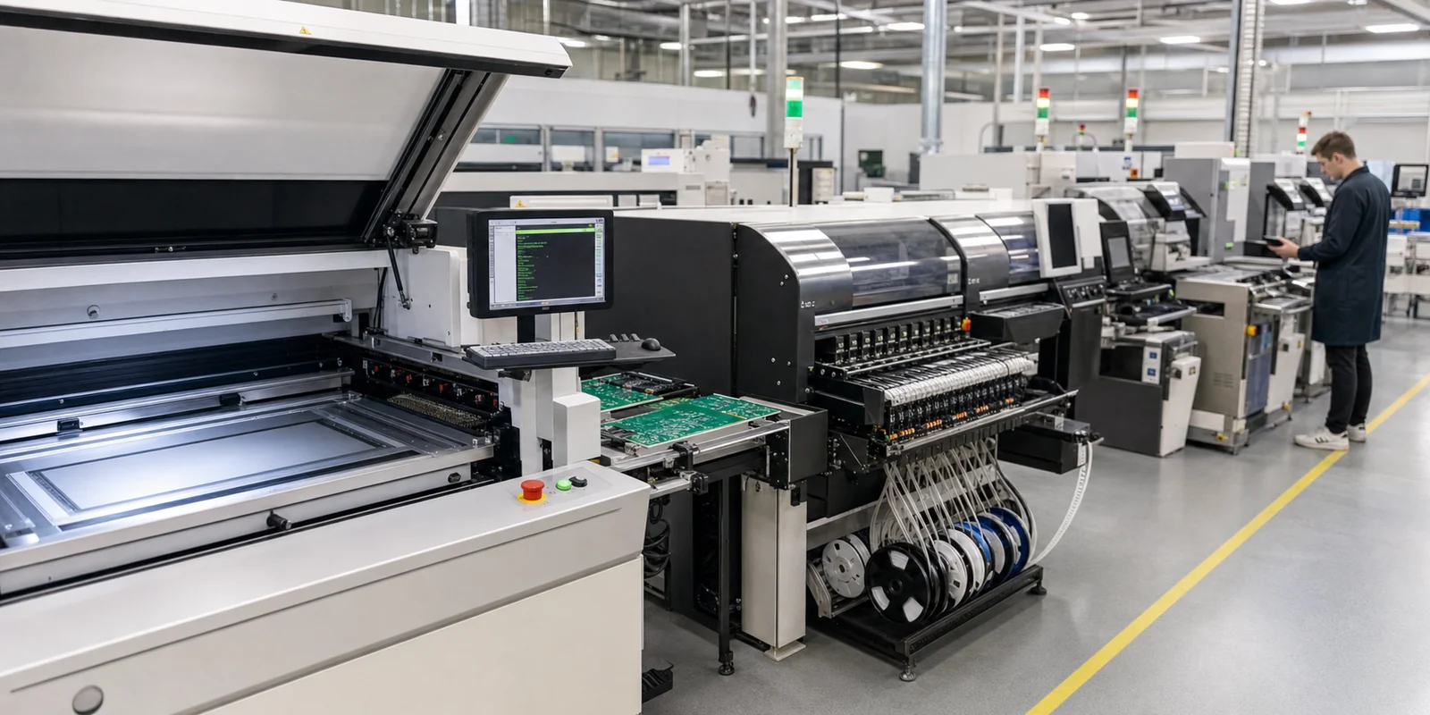
A wave soldering machine still earns its place in PCB assembly, but not for the reasons many factories assume. The machine is valuable when the board mix still matches the process: enough through-hole density, manageable bottom-side risk, good drainage geometry, and realistic masking strategy. When those conditions are missing, the machine can become an expensive way to create bridges, scorched residues, and rework that should have been prevented in design review.
That is why equipment choice should start with board compatibility, not nostalgia or habit. ReversePCB already has a broader wave soldering guide. The narrower question here is when a wave soldering machine still makes sense as a production asset, how its process zones affect joint quality, and what engineers should check before assuming it is the right answer for modern through-hole builds.

When a wave soldering machine still makes practical sense
A wave soldering machine is strongest when the product family still has meaningful through-hole content and the board layout allows solder to contact the right pads without exposing fragile bottom-side SMT parts. Power supplies, industrial controls, heavier connectors, and legacy mixed assemblies often still fit this model. In those cases, one pass through a controlled flux, preheat, and wave sequence can be faster and more economical than treating every joint as a selective-solder event.
The mistake is assuming that all mixed-technology boards still belong there. Dense bottom-side SMT, large shadowing parts, awkward connector orientation, or tight cleanliness requirements can quickly turn the process into a masking and touch-up exercise. Once that happens, the question is no longer whether the machine can run the board. It is whether the board should be on that machine at all.
Which machine zones matter most to joint quality
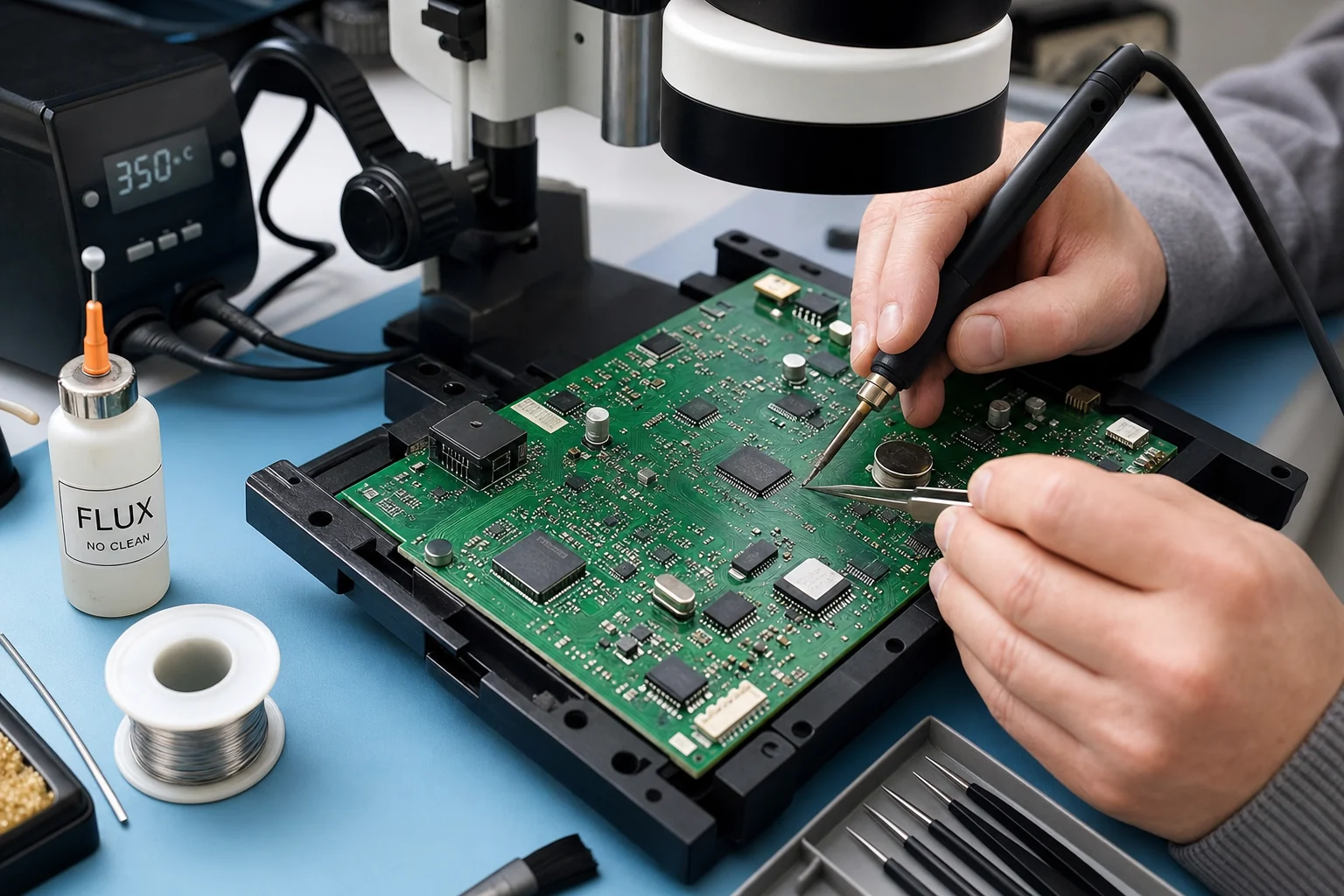
Fluxing quality decides whether the rest of the process has a chance
Weak or uneven flux application often looks like a solderability problem later. If activation is inconsistent across the board, some holes fill cleanly while others lag or trap voids. Engineers should pay attention to spray uniformity, maintenance cleanliness, and how the chosen flux interacts with the actual finishes, not just the datasheet promise.
Preheat is where many process windows quietly widen or collapse
Preheat does more than warm the board. It drives off volatiles, activates flux, and reduces thermal shock before contact with the solder wave. If preheat is too weak, flux may not do enough work and solder can wet poorly. If it is too aggressive, residues char and plastic-bodied components or nearby adhesives can enter the wave stage already overstressed. A machine that cannot keep preheat repeatable will force operators into unstable compromises downstream.
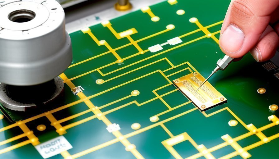
Wave shape, contact time, and conveyor stability are linked
Engineers often debate single wave versus dual wave settings, but the real issue is whether the solder contact matches the board geometry. Conveyor angle, travel speed, wave height, and dwell time all affect bridging, solder icicles, and hole fill. Even good settings lose value if pallets or support rails let the board shift. Mechanical stability matters here just as much as thermal tuning.
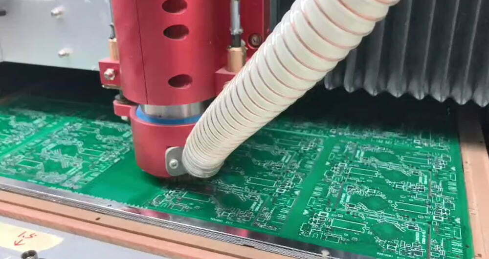
Why board design can make or break the machine decision
Component orientation, lead protrusion, pad geometry, and drainage direction all decide how well solder can leave the joint after contact. If connectors, transformers, or tall parts create shadowing, the machine may be blamed for a design problem it cannot solve. The same applies to bottom-side SMT parts that sit too close to the wave path or require excessive masking.
This is also why the process should be reviewed alongside through-hole versus surface-mount tradeoffs and broader flux selection decisions. A wave soldering machine performs best when the board was designed with drainage, support, and exposure in mind rather than adapted to the machine after layout is finished.
Common failure patterns that point to process mismatch
- Bridging that clusters around connector rows or closely spaced through-hole pins.
- Inconsistent hole fill on heavier copper or high-thermal-mass locations.
- Bottom-side residues or solder disturbance near sensitive SMT components.
- Frequent pallet changes and manual masking that erase the machine’s throughput advantage.
- Rework technicians spending more time correcting predictable wave-related defects than the line saves in cycle time.
These are all signs that the machine may still be functioning correctly while the product fit is deteriorating. That is an engineering decision problem, not only an equipment one.
Questions to ask before approving a board for wave soldering
- How many through-hole joints actually benefit from one-pass wave processing on this board?
- Which bottom-side SMT parts, if any, are exposed to wave or heat risk?
- Does the board need extensive masking or a custom pallet to survive the pass?
- Are component orientation and lead lengths optimized for solder drainage?
- Can flux, preheat, and conveyor settings stay stable across the full product family?
- Would selective soldering reduce total rework and masking effort even if cycle time looks slower on paper?
When those answers are honest, the decision becomes clearer. Some boards still fit wave soldering extremely well. Others only appear to fit until the inspection data starts climbing.
The machine is valuable when the board still deserves it
A wave soldering machine is not obsolete, but it is no longer the automatic answer for every through-hole or mixed-technology assembly. It creates real value when board design, fixture support, fluxing, preheat, and solder drainage all pull in the same direction. When they do not, the process quickly turns into controlled damage. The best factories keep the machine for the right boards and refuse to force the wrong ones through it just because the equipment is available.