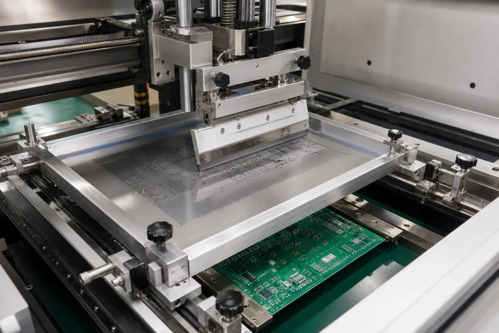
SMT stencils decide print quality before the reflow oven ever gets a vote. Every placement machine, inspection station, and solder profile downstream has to live with the paste deposits the stencil printer creates. If the stencil is wrong for the board, the process may still appear stable for a few panels, but the defects usually show up later as bridges, insufficient joints, voiding, skewed passives, or a rework load that nobody wants to trace back to the print stage.
That is why stencil selection is not just a purchasing line item. Engineers need to think about foil thickness, aperture behavior, board support, and cleaning discipline as one system. ReversePCB has already covered solder paste inspection and broader SMT assembly flow, but SMT stencils deserve their own treatment because poor print transfer can make a healthy line look inconsistent long before the real cause is found.
Why stencil decisions carry more weight than many teams expect
A stencil determines paste volume, release behavior, and positional accuracy before any component is placed. If apertures are too aggressive, small pads can bridge or slump. If they release poorly, solder joints start life short on volume and become vulnerable to opens or weak wetting during reflow. The rest of the line can only compensate so much. A better oven profile will not fix missing paste, and a faster placement machine will not correct a poor aperture design.
This matters most on boards that mix fine-pitch QFPs, BTC or QFN packages, small passives, and large thermal pads. One stencil has to support all of them. That is why experienced process engineers treat stencil design as a yield-control tool rather than as a commodity accessory.
How to choose SMT stencils without creating print conflict
Stencil thickness should follow the hardest release problem
Teams often start with a standard foil thickness and only revisit it after print defects show up. A better approach is to identify the smallest or most release-sensitive apertures first, then ask how the larger pads will be handled. If one thick stencil helps large pads but starves fine-pitch parts, the board has not been optimized. It has only moved the defect to a different location.
Aperture design usually solves more than brute-force paste volume
Large thermal pads, shield tabs, and power devices often need segmented apertures or reduced area ratios rather than one oversized opening. Paste release, slump, and voiding behavior all matter. Engineers should prefer aperture changes that create stable deposits instead of simply pushing more paste and hoping reflow will sort it out.
Board support and print mechanics matter as much as foil quality
Even a high-quality stainless stencil will print badly if the PCB flexes under squeegee pressure. Support pins, vacuum tooling, rail setup, and separation speed all affect transfer efficiency. On thinner boards, poor support can make aperture alignment look fine in setup and still create inconsistent deposits once production starts. A good stencil specification should always be paired with a realistic print setup review.
Cleaning frequency is part of stencil selection, not an afterthought
Some aperture patterns are more tolerant of longer print runs than others. Others trap paste quickly and need more frequent underside cleaning to avoid build-up and partial blockage. If the line cannot maintain the cleaning interval a stencil really needs, the issue is not just operator discipline. It may also be a sign that the stencil design is too fragile for the production environment.
When a step stencil is worth the extra complexity
A step stencil becomes useful when one board genuinely needs very different paste volumes in different zones. Fine-pitch components may require thinner foil behavior, while large thermal pads or connector tabs may need more deposit height. In that case, a step-up or step-down region can widen the process window.
But a step stencil should solve a specific print conflict, not serve as a fashionable upgrade. It adds fabrication cost, setup sensitivity, and sometimes cleaning complications. If the board can be stabilized with aperture optimization and better print support, that is usually the simpler path.
Defects that often point back to the stencil stage
- Repeat bridges on fine-pitch devices even when placement accuracy and reflow profile look normal.
- Insufficient solder on small passives or QFN perimeter pads despite acceptable paste volume elsewhere.
- Large thermal pads that show chronic voiding or unstable collapse from build to build.
- Print quality that drifts across longer runs because apertures contaminate faster than the cleaning cycle allows.
- Operator adjustments that keep changing squeegee pressure or alignment without fixing the root cause.
Those symptoms are easy to mislabel as paste or reflow problems, but the stencil is often where the process window narrowed first. If the print stage is unstable, later process tuning becomes expensive guesswork.

Questions to ask before approving a stencil for production
- Which apertures on this board have the weakest area ratio or most difficult release behavior?
- What board support method will be used during printing, and does it match the real panel stiffness?
- Are large pads segmented for release control, or is paste volume being pushed too aggressively?
- How often will underside cleaning be required at realistic line speed?
- Does the design need a step stencil, or can aperture changes solve the same issue more simply?
- What inspection evidence will confirm the print transfer is stable before full release?
When those answers are clear, SMT stencils stop being a hidden source of variation and start acting like the process-control tool they should be.
Good paste prints usually begin with disciplined stencil choices
SMT stencils deserve more engineering attention than they usually get because the print stage sets the physical starting point for every solder joint that follows. If foil thickness, aperture strategy, board support, and cleaning discipline are chosen with the product in mind, the rest of the SMT line has a much better chance of staying predictable. If they are treated as defaults, the factory often pays for that shortcut later in scrap, escapes, and rework hours.
What does an SMT stencil do in PCB assembly?
An SMT stencil controls where solder paste is deposited and how much paste reaches each pad before placement and reflow. In practice, stencil thickness, aperture geometry, and print support have a direct effect on bridges, opens, voiding, and rework.
How do you choose SMT stencil thickness?
Stencil thickness should match the smallest aperture challenge and the larger paste-volume needs on the same board. Fine-pitch parts often push thickness downward, while large thermal pads may need aperture design changes instead of simply making the whole stencil thicker.
When is a step stencil worth using?
A step stencil becomes useful when one product needs very different paste volumes in different areas, such as fine-pitch components next to large power pads or shielding tabs. It adds cost and setup complexity, so it should solve a real print limitation rather than serve as a default upgrade.
Why do good SMT stencils still produce bad paste prints?
Because stencil quality is only one part of the print system. Board support, squeegee condition, paste rheology, alignment, cleaning frequency, and separation speed can all ruin deposits even when the stencil itself was manufactured correctly.