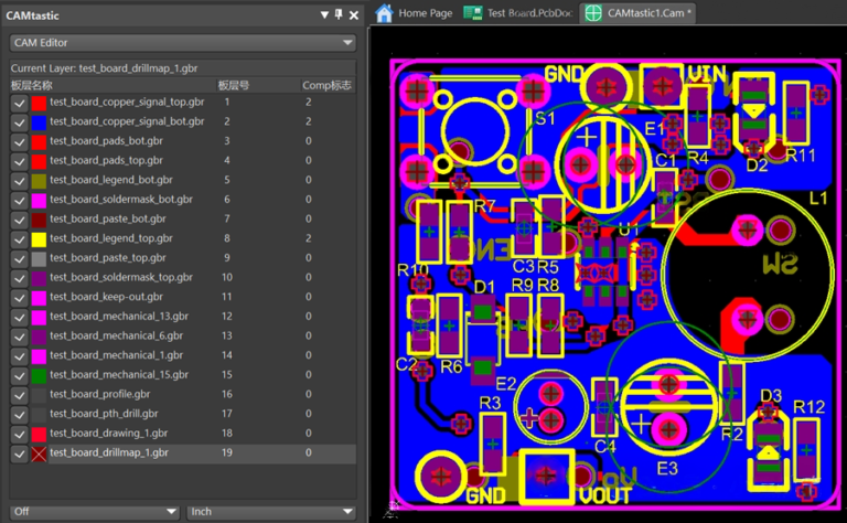
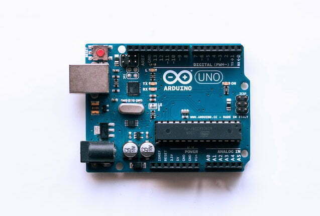
In the design and manufacturing of Printed Circuit Boards (PCBs), choosing the most appropriate layout file to convey schematic and manufacturing instructions is added to the degree of accuracy of the end product. Different file formats have different functions and these should be understood clearly to avoid any misinterpretation by PCB manufacturers. In this article, we describe four most relevant file types, each one intended for specific uses in PCB designing and making.
Gerber Files
Gerber files are the industry standard for describing PCB layers, such as copper layers, solder masks, and silkscreens. Developed by Gerber Systems Corp., they are widely compatible with most PCB design and manufacturing tools.
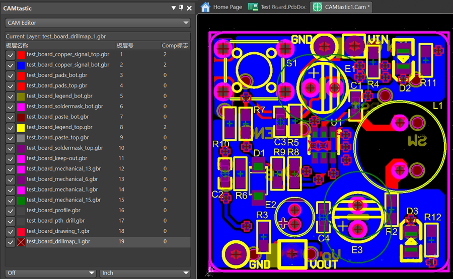
RS274-D is the standard Gerber file format, using a numerical control format composed of XY coordinates and drawing codes, and is represented by the extension “.gbr“. It was initially very popular, but this format required manual assignment of aperture codes to generate accurate Gerber files, leading to the development of an extended Gerber format.
RS274-X is the revised version, with the extension “.gbx“, using an ASCII format that integrates the four main parts of Gerber information (configuration parameters, aperture information, XY coordinates, and drawing commands) into a single file. In this format, aperture positions are updated automatically.
Advantages:
- Compatibility: Supported by the majority of PCB design and manufacturing software.
- Established History: Gerber has been used in the industry for many years, providing stability and reliability.
Limitations:
- Lack of Metadata: Original Gerber files contain minimal metadata, which can lead to misinterpretations.
- Complex File Management: Each PCB layer requires a separate file, making management more complex.
Still confused? read our Comprehensive Introduction of Gerber Files.
Gerber X2 Files
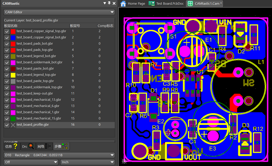
Gerber X2 is an enhanced version of the original Gerber format. It includes additional metadata such as layer stack details, via and pad attributes, impedance-controlled traces, and more. These features can help improving data accuracy and reduce errors during manufacturing. Supported extensions include “.top“, “.bot“, etc. This format is backward compatible with RS274-X but contains a wealth of manufacturing data, significantly reducing file errors and data ambiguity.
Advantages:
- Improved Data Clarity: Includes layer names and comments, helping manufacturers interpret the design more easily.
- Backward Compatibility: Can be used with older Gerber systems, while providing extra features for modern designs.
Limitations:
- Adoption Challenges: Older systems may not fully support Gerber X2, requiring conversion or updates.
ODB++ Files
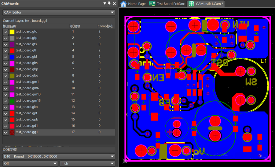
Developed by Valor, ODB++ is a comprehensive file format that consolidates all PCB design information into a single file, including layers, component placements, and assembly instructions.
More info about ODB++ file
Advantages:
- Data Consolidation: Combines all necessary design and manufacturing details into one file.
- Streamlined Manufacturing: Reduces the need for clarifications between design and production, optimizing the workflow.
- Advanced Features: Supports complex designs and enables higher levels of automation.
Limitations:
- Limited Adoption: Less common than Gerber files, meaning some manufacturers may require additional tools or conversions.
IPC-2581 Files
The IPC-2581 format is an open and neutral file format developed by the IPC, the association that connects electronics industries. It standardizes PCB design and manufacturing data.
More info about IPC-2581 file
Advantages:
- Standardization: Ensures consistency and compatibility across various design and manufacturing tools.
- Comprehensive: Provides a complete description of the PCB, including electrical, mechanical, and manufacturing details.
- Open Format: Encourages broader adoption and integration across the industry.
Limitations:
- Lower Adoption: While it offers significant advantages, it is less widely supported compared to Gerber formats.
Drill Files
Drill files, such as NC Drill and Excellon files, provide instructions for drilling holes in the PCB, which is crucial for interconnecting layers and securing components.
- NC Drill Files: These files are designed to control the motion and parameters of CNC drilling machines, specifying coordinates, hole diameters, and depths.
- Excellon Files: Similar to NC Drill files, Excellon files are used to control CNC machines for both drilling and cutting PCBs.
Conclusion
The proper file format for the PCB schematic and structure of the manufacturing data is to be chosen with the importance of accuracy in the production of your product. Although Gerber files remain the most prevalent because of their compatibility and industry familiarity, there is improved data with Gerber X2, ODB++, and IPC-2581 for more complex design solutions.

