How to Read Electrical Schematics: A Practical Guide for Circuit Work
Electrical schematics can look dense at first: lines crossing the page, symbols instead of physical parts, reference designators everywhere, and power rails that seem to disappear and reappear. The useful trick is to stop reading a schematic like a picture of the board. A schematic is not a map of where parts sit. It is a logic diagram that shows how voltage, current, and signals move through a circuit.

Once you read it that way, the drawing becomes much less intimidating. You can trace the power path, identify functional blocks, check component values, and connect the diagram back to the real PCB. That skill matters whether you are debugging a damaged board, reviewing a design before layout, or preparing files for PCB design service.
Start With the Title Block and Sheet Context
Before following any wire, look at the title block. It usually tells you the project name, drawing number, revision, sheet number, and sometimes the engineer or date. Those details sound administrative, but they prevent real mistakes. If you are repairing equipment, one revision difference can change a connector pinout or a protection circuit. If you are comparing a board against a drawing, the wrong schematic revision can make a good board look wrong.
Multi-page schematics often split the design into sheets such as power input, microcontroller, analog front end, communications, motor drive, or connectors. Do not assume the first page is the whole circuit. A signal may leave one page through a net label and continue on another page. When a design has many pages, build a quick mental index of the major blocks before reading details.
Learn the Most Common Symbols First
You do not need to memorize every symbol before you can read a useful schematic. Start with the common parts:
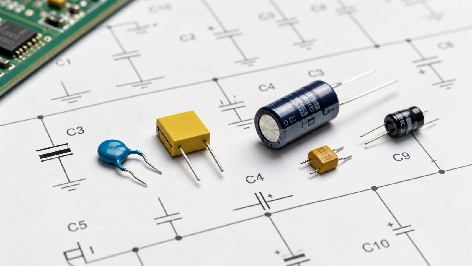
- Resistors are usually zigzag or rectangular symbols and are marked with
Rdesignators. - Capacitors are two parallel plates and are marked with
Cdesignators. - Diodes show a one-way current direction and use
Ddesignators. - Transistors often use
Q, while MOSFETs add gate, drain, and source pins. - Integrated circuits use
UorIC, and their pins may be spread across several symbol units. - Connectors use
J,P, orCN, depending on the drawing convention. - Grounds, chassis grounds, and earth grounds may use different symbols and should not be treated as identical without checking the design.
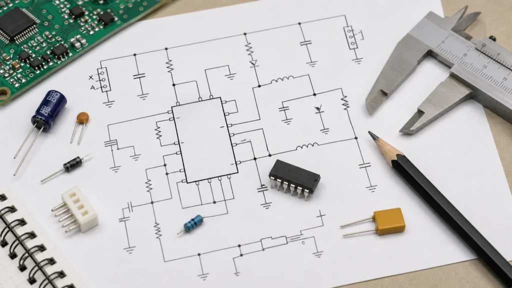
When the schematic moves from symbol to actual hardware, reference designators become your best friend. If the diagram says R47, you can search the PCB silkscreen or assembly drawing for R47. For physical identification, a companion guide to circuit board components can help connect schematic symbols to the parts you see on the board.
Read Power Before Signals
A reliable way to approach almost any schematic is to read power first. Find the input source: battery, DC jack, AC adapter, terminal block, USB connector, or mains supply. Then follow the protection and conversion stages. You may see fuses, transient-voltage suppressors, reverse-polarity protection, rectifiers, regulators, DC-DC converters, ferrite beads, or local decoupling capacitors.
Power nets usually have names like VIN, VBAT, +12V, +5V, 3V3, VDD, AVDD, or VREF. The exact names matter. A board may have both noisy digital 3.3 V and cleaner analog 3.3 V rails. If you miss that distinction, troubleshooting can go sideways quickly.
After you identify the rails, ask practical questions:
- What voltage enters the board?
- What protection exists before the first regulator?
- Which regulator creates each rail?
- Which loads sit on each rail?
- Is there an enable pin or power-good signal that controls startup?
- Are analog and digital rails separated by filters or ferrite beads?
This first pass often reveals why a board will not start. A missing enable signal, shorted output capacitor, open fuse, or wrong input polarity can all be found faster when you read power as a sequence instead of staring at the whole drawing.
Follow Net Names, Not Just Lines
In small circuits, wires may be drawn directly from one component to another. In larger schematics, that becomes unreadable, so designers use net labels. A label such as I2C_SCL, MOTOR_PWM, RESET_N, or ADC_IN1 means every point with the same label is electrically connected, even if there is no visible line between them.
This is where beginners often get stuck. They follow a drawn line until it ends, then assume the signal ends too. In reality, the signal may continue through a page connector, hierarchical port, or global net label.
Pay attention to naming patterns. A suffix such as _N or a bar over a signal often means active-low logic. TX and RX labels are relative to a device, so the transmitter of one IC should connect to the receiver of another. Differential pairs may appear as USB_D+ and USB_D-, CANH and CANL, or CLK_P and CLK_N. These paired signals should be treated together when you later inspect routing and PCB trace basics.
Break the Schematic Into Functional Blocks
Trying to understand every component one by one is slow. Instead, divide the schematic into blocks and give each block a job. A typical embedded board might include:
- Input protection and power regulation
- Microcontroller or processor
- Clock and reset circuit
- Programming/debug connector
- Sensors or analog conditioning
- Communications interfaces such as UART, SPI, I2C, CAN, USB, or Ethernet
- Output drivers for relays, motors, LEDs, heaters, or solenoids
- Test points and production fixtures
Once you know the blocks, the schematic starts to read like a system. The microcontroller does not exist in isolation; it reads sensors, drives outputs, communicates with external devices, and depends on stable power and clock signals. If one block fails, the schematic lets you ask what it needs from neighboring blocks.
Interpret Component Values and Design Intent
Values are not decoration. A 10 kOhm resistor may be a pull-up, pull-down, divider leg, bias resistor, or current limiter depending on where it sits. A 100 nF capacitor near an IC power pin is probably decoupling. A large electrolytic near a connector may absorb load transients. A series resistor on a microcontroller pin may reduce ringing, limit fault current, or protect against ESD events.
Look for repeated patterns. If every IC has a 100 nF capacitor from VDD to ground, that is local bypassing. If each external connector line has a small resistor, TVS diode, or common-mode choke, that is interface protection. If a MOSFET gate has a resistor and pull-down, the designer is controlling switching behavior and startup state.
This is where schematic reading becomes engineering judgment. You are not only asking, “What is connected?” You are asking, “Why did the designer connect it that way?” That habit is especially useful before PCB assembly, because missing values, ambiguous polarity, and unclear reference designators can turn into production delays.
Use Datasheets Alongside the Schematic
When an IC is central to the circuit, open the datasheet. The schematic alone may show the connections, but the datasheet explains the rules: supply range, pin functions, boot mode pins, oscillator requirements, recommended decoupling, thermal limits, layout notes, and timing behavior.
Compare the schematic against the typical application circuit. You do not need to copy the datasheet blindly, but differences should have a reason. If the datasheet recommends a pull-up on a reset pin and the schematic has none, check whether the IC includes an internal pull-up. If a switching regulator has compensation components, verify they are not arbitrary values copied from another design.
For repair work, datasheets also help you choose measurement points. If a regulator should output 3.3 V only when EN is high, measure both the output and the enable pin. If a microcontroller will not boot unless reset is released and the clock runs, check those pins before replacing the IC.
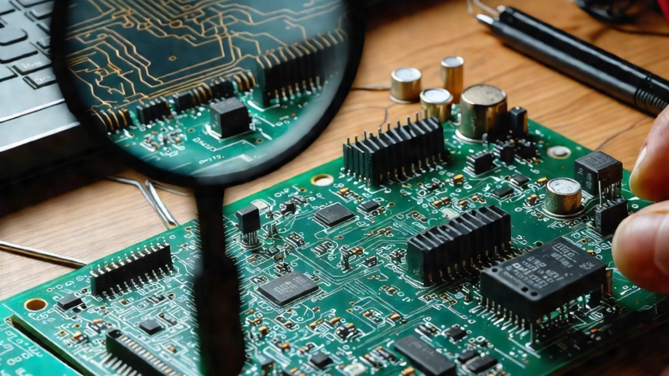
Connect the Schematic Back to the PCB
A schematic tells you electrical intent, while the PCB shows physical implementation. To troubleshoot or reverse engineer a board, you need both views. Start with a known component, such as a connector, regulator, or microcontroller. Match its reference designator between the schematic and the board. Then trace nearby components by designator and net function.
Some nets are easy to locate with a multimeter continuity mode. Ground, power rails, fuse paths, connector pins, and large traces are usually straightforward. Fine-pitch IC pins, buried vias, and internal layers require more care. If no original drawings exist, professional PCB reverse engineering may be needed to reconstruct the schematic from the physical board.
Do not assume layout proximity equals schematic proximity. A capacitor drawn far from an IC may be physically right next to it on the PCB. A connector pin drawn on page one may route to circuitry on page five. The schematic shows relationships; the layout shows placement and routing constraints.
Check Polarity and Direction Carefully
Many schematic mistakes and repair errors come from polarity. Electrolytic capacitors, diodes, LEDs, bridge rectifiers, MOSFET body diodes, optocouplers, and connectors all have direction or orientation. A symbol may be electrically clear but physically easy to misread.
Watch for these details:
- Diode cathodes are usually marked by a line on the symbol and a stripe on the part.
- Electrolytic capacitors have polarity markings, and the schematic may mark the positive side.
- MOSFET source and drain orientation matters, especially because of the body diode.
- Connector pin 1 must match the mating cable or enclosure orientation.
- Active-low signals may look “off” when they are electrically asserted.
When in doubt, compare the schematic, PCB silkscreen, component datasheet, and actual measured voltage. A single assumption about polarity can damage a replacement board or hide the real fault.
A Practical Reading Sequence
For a new schematic, use this repeatable sequence:
1. Check title block, revision, and sheet list. 2. Identify input power and all generated rails. 3. Find the main controller or functional center of the design. 4. Group the circuit into power, control, input, output, communications, and protection blocks. 5. Follow critical nets by label across sheets. 6. Read component values in context, not in isolation. 7. Use datasheets for IC pins and recommended circuits. 8. Map important reference designators back to the PCB. 9. Verify polarity, connector pinout, and test points before powering or replacing parts.
The goal is not to memorize the whole schematic. The goal is to build a useful model of how the circuit should behave, then use that model to design, inspect, assemble, or repair the board with fewer guesses.
Final Thoughts
Reading electrical schematics is a practical skill, not a one-time theory lesson. The more circuits you inspect, the faster you recognize power trees, reset circuits, communication buses, analog filters, driver stages, and protection networks. Start with the big blocks, follow named nets carefully, and keep datasheets close. Once the schematic begins to feel like a circuit story rather than a page of symbols, debugging and PCB work become much more controlled.
What is the first thing to identify on a schematic?
Start with power rails, ground symbols, connectors, and the main functional blocks. These give you a reference before tracing signals through smaller parts.
How do I match schematic symbols to a real PCB?
Use component designators such as R, C, U, D, and J, then compare the PCB silkscreen, package shape, and nearby connected traces. A board view or BOM makes this much faster.
Why is ground reference important when reading schematics?
Most voltage measurements and signal paths only make sense relative to a reference node. If you pick the wrong ground or return path, the reading can look like a circuit fault when it is actually a measurement mistake.