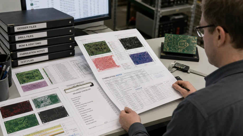
A Gerber file does not prevent PCB manufacturing delays by itself. Delays happen when the release package looks complete to the designer but still leaves the fabricator guessing about drill intent, stackup assumptions, impedance targets, solder mask behavior, or assembly-critical notes. That is why one board package sails through CAM review while another triggers questions, hold points, or an avoidable respin. This guide explains what a Gerber file set needs to do in real production, why Gerber files fail handoff so often, and how to release fabrication data that a board shop can act on without risky assumptions.
A Gerber file is only one part of the manufacturing package
The base Gerber layers describe copper, solder mask, silkscreen, and other imaged artwork, but fabrication still depends on everything surrounding those layers. Drill data, stackup notes, material calls, finish requirements, controlled-impedance targets, routing tolerances, panel guidance, and readme-level instructions all affect whether the board can be built correctly. If those items are inconsistent or missing, the supplier has to infer intent, and that is where schedule risk starts.
Design teams sometimes believe that exporting Gerber files means the job is ready. In practice, export is only the first checkpoint. The real question is whether the release package answers the board shop’s manufacturing decisions clearly enough to survive CAM review without a chain of clarification emails.
What typically goes wrong in a Gerber handoff
Most failures are not exotic. They come from ordinary mismatches between what layout intended and what fabrication needs to know. A file set can look visually correct and still be weak as a manufacturing release if the supporting details are vague.
Drill data does not match pad intent
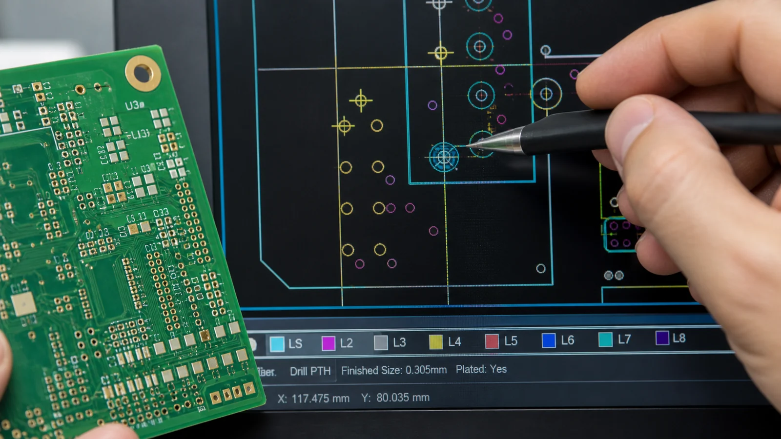
One common problem is a drill file that technically exists but does not clearly align with the pad stack decisions on the board. Finished hole expectations, slot definitions, buried or blind via assumptions, and plating intent all need to be interpretable without guesswork. If the board includes dense via fields or unusual hole structures, the fabricator should not have to reverse-engineer the design from layer art alone.
Stackup and impedance information live somewhere else
Gerber layers do not tell the fabricator what dielectric thickness, copper weight, or impedance structure the product requires. When the release package omits that information or buries it in an outdated note, CAM review slows down immediately. The board shop may be able to propose a reasonable default, but that default can shift trace impedance, copper balance, or lamination choices in ways the design team never intended.
Solder mask and silkscreen are treated as cosmetic
Mask clearance and legend placement can create real assembly problems when they are released without review. A silkscreen mark that overlaps a pad, a mask opening that weakens a fine-pitch area, or a polarity indicator that disappears after assembly cleanup is not a documentation problem. It is a manufacturing and service problem. That is why mask and legend outputs deserve the same release discipline as copper and drill data.
Why CAM review catches issues the export step never will
Export tools confirm that files were generated. CAM review checks whether the package behaves like a manufacturable instruction set. The distinction matters. A CAD tool can happily output every layer while leaving unresolved questions about annular ring margin, slot interpretation, net tie geometry, or whether the solder mask opening near a BGA field is still safe after fabrication tolerance is applied.
That is why engineers should treat CAM findings as a release-quality signal, not as vendor inconvenience. If the board shop asks several basic questions before quoting, the data package probably needs work. The fastest quote often goes to the team whose release package reduces ambiguity before it reaches fabrication engineering.
What a solid Gerber release package should include
A strong release package does more than bundle the right file extensions. It tells the fabricator what matters most and what should never be assumed away during preprocessing.
- Gerber artwork for every required layer, with naming that does not force the vendor to decode your internal shorthand.
- NC drill or equivalent drill data that clearly distinguishes plated, non-plated, slot, and special-feature intent.
- Stackup information with dielectric assumptions, copper weight, board thickness target, and any controlled-impedance context.
- Fabrication notes covering finish, mask color if relevant, panel constraints, test coupon expectations, and special process callouts.
- Assembly-facing context when the board has pad, polarity, or package behaviors that should influence mask, legend, or flatness review.
- A version-controlled readme or release note that names the authoritative package and prevents suppliers from quoting an outdated export.
For dense layouts, it also helps to confirm that the release reflects the same via strategy, stackup logic, and fabrication assumptions used during design review. If the board depends on HDI features, via-in-pad behavior, or controlled-impedance geometry, those dependencies should be obvious in the release package rather than implied.
Version control mistakes can be as expensive as layout mistakes
One of the most expensive release failures is sending the wrong revision, or sending the right revision with one old support file still attached. A stale drill file, outdated fab note, or previous stackup screenshot can produce a package that appears internally consistent until the board shop begins preprocessing. The resulting confusion wastes time and can damage confidence in the release process even if the design itself is sound.
That is why disciplined teams freeze the release package as a single named revision, not as a loose collection of exports from different dates. When a board is being quoted by multiple suppliers, that discipline becomes even more important because quote comparisons are meaningless if each vendor is interpreting a slightly different package.
How assembly and service teams benefit from a better Gerber package
A better fabrication package does not only help the board shop. Assembly teams benefit when mask openings, reference designators, polarity marks, and land behaviors have been released carefully. Service teams benefit when test points, connector orientation cues, and readable legend survive the real manufacturing process. Many field-debug frustrations start with release decisions that treated assembly and maintenance details as secondary.
This is one reason Gerber release quality should be reviewed together with the broader PCB via overview, the HDI PCB guide, and the stackup tradeoff guide. Manufacturing files are only reliable when they reflect the same engineering decisions those design reviews already made.
Release Gerber files as manufacturing instructions, not just exported artwork
The best Gerber file package is the one that reduces interpretation. If the board shop can identify layer intent, drill structure, stackup assumptions, finish requirements, and special process risks without guessing, the quote moves faster and the build starts from a cleaner baseline. If the package leaves those items unclear, even a good layout can drift into delay or respin. Gerber files matter, but the release discipline around them matters more.
FAQ
Are Gerber files enough to manufacture a PCB?
Usually not by themselves. Fabrication also depends on drill data, stackup information, finish requirements, notes about controlled impedance or special structures, and clear revision control so the supplier knows which package is authoritative.
Why do Gerber files still cause delays if the layers export correctly?
Because export success does not guarantee manufacturing clarity. Delays usually come from missing drill detail, ambiguous stackup assumptions, mismatched notes, version confusion, or mask and legend issues that only become obvious during CAM review.
What is the most common Gerber handoff mistake?
A common mistake is sending artwork files that do not stay synchronized with the drill set, fabrication notes, or final revision package. The board shop then has to ask which files are authoritative before quoting or tooling the job.
Should designers review Gerber files before sending them to fabrication?
Yes. A visual and manufacturing-oriented review is worth doing every time, especially for mask clearance, drill interpretation, polarity legend, impedance notes, and any HDI or special-via structure. Export is not the same as release validation.