Embedded systems design and development are driven by application requirements and IT technologies. With the continuous innovation and development of microelectronics technology, the integration level and process level of large-scale integrated circuits have been continuously improved. In particular, the introduction of embedded real-time operating system (RTOS) provides the underlying support and high-efficiency development platform for the development of complex embedded system application software.
Embedded Systems Design process
Design Phase
The initial phase of conceptual design of a new product involves some foresight of the product based on market predictions, customer needs, and technology development. When planning a product, a business case is made for the product with estimates of the number of sales units, price, and profit. This leads to the creation of an initial product layout, design specification, and product marketing plan. At this stage, industrial designers may also be involved to create a new product packaging concept.
Don’t forget that the sales price must cover the company’s marketing, design, and development costs in addition to the cost of manufacturing each product unit. This depends on the volume of sales, but a price level of two or three times the cost of producing a unit of product is not unusual.

Development Phase
Most of the hardware and software implementation efforts occur at the end of the design phase and during the development phase. Critical analysis of design decisions helps determine whether it is physically possible to implement a project concept based on project specifications. Electrical and software mockups are often created before analyzing design decisions. Then a small number of prototypes are designed, constructed, and used for more detailed hardware and software testing.
production phase
Finally, in the production phase, a large amount of product is produced. First, a small pilot batch is usually created for additional testing and evaluation before mass production begins. Quality engineers continuously work to improve the quality of the product and process. Support engineers deal with changes that follow the introduction of a new product and provide technical support for the product. Given the current trends of globalization, mass production of a new embedded device often takes place in another country where it is more cost-effective. For many embedded devices, the entire process takes anywhere from six months to a year, but the competitive market is constantly forcing a shorter product lifecycle.
Developing an embedded system project
The main software development and engineering design efforts occur in the development phase, which will now be described in more detail. First of all, designers must choose the processor and operating system. Choosing a processor for an embedded device involves many factors to consider, such as price, performance, power consumption, and software support.

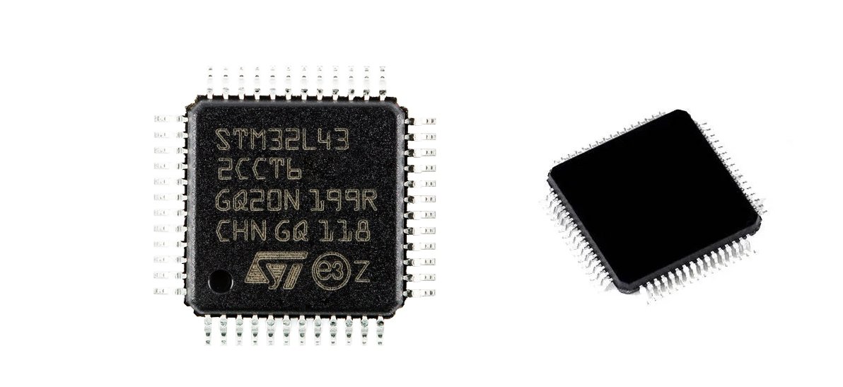
choose the processor
Manufacturers provide manuals describing their processors and usually provide developers with a complete development of a reference board that can be used as a starting point when developing a new computer design that uses this processor. A detailed description of each individual processor, memory device, and all the required chips is beyond the scope of this guide, but some of the most general hardware properties that directly affect software creation will be discussed later.
connect hardware devices to the processor
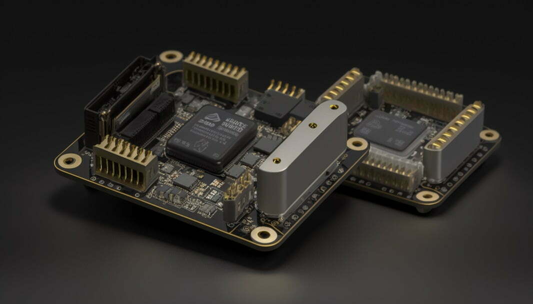
After the embedded system hardware designer has selected the processor and its corresponding memory devices, the next step is to add the hardware I / O devices and the corresponding bus structure needed to connect the required devices to the processor. The design of embedded devices involves selecting and connecting the hardware required for various I / O devices required in the new design.
Test, debug, and redesign
After carefully entering the schematic diagram of the design, a printed circuit board (PCB) is designed for the embedded device using a computer-aided design system (CAD) of printed circuit boards. This tool imports pin connection information from a circuit diagram and uses it to design and test the copper conductors used to connect integrated circuits (ICS) on a printed circuit board. Several printed circuit boards are created, filled with the necessary components, and then used to perform extensive software tests on the new design. Any hardware design errors detected during testing will require a change in the circuit diagram, modification of the printed circuit board design, and a new one.This will increase the production cycle of printed circuit boards and testing, which will increase the development time accordingly.
choose the operating system
Software development tools are usually shipped with the OS. Since the OS is written in C / C++, generating a new OS requires a compiler, link editor, debugger, and binary image tools. The same tools are usually used for application development.
Software development takes place in parallel with hardware development in order to reduce the total product development time. This becomes even more important given the ever-shrinking product lifecycle of today’s embedded devices. For software development and testing, you can use emulation tools and embedded computer boards with similar hardware running the same OS before a new hardware platform becomes available. Since most of the code is written in C / C++/C#, most of the software can even be developed and tested on another processor or emulator. The code is then recompiled for the new processor for the last round of development and testing when new hardware becomes available.
When you have completed the development of your software, you can transfer it to a real device for testing and final release. Windows Embedded CE has an ARM emulator along with development tools. The emulator enables you to run your software on a PC at much higher speed than real hardware. The emulator can be used for debugging and profiling your software, and it can also be used for software development for remote devices.
Memory technologies for embedded devices
Most embedded devices currently use two types of memory, SDRAM or sometimes possibly SRAM for main memory and Flash or ROM for non-volatile memory. SDRAM has a significantly lower cost per bit of memory than SRAM, but requires a more sophisticated hardware controller for periodic dynamic memory update cycles. One of the most important decisions that must be made at the beginning of the design process is how much memory of each type the device needs.
SDRAM memory
SDRAM is the abbreviation of Synchronous Dynamic Random Access Memory. It uses a 3.3v working voltage and a bandwidth of 64 bits. It’s also the mainstream memory for a long time, from the 430TX chipset to the 845 chipset all support SDRAM. The SDRAM locks the CPU and RAM together through the same clock, so that the CPU and RAM can share a clock cycle and work synchronously at the same speed. The rising edge of each clock pulse starts to transfer data, and the speed is 50% higher than that of EDO memory.
Flash memory
The operating system and application programs are usually stored in flash memory, since most embedded devices do not have a hard disk device.
Flash memory devices store data on flash chips. Flash chips contain a pattern of electrons that move in a loop. The electrons are stored in the memory cell and move back and forth between the different bits of data on the chip. The number of bits is measured by how fast the electrons move between cells, or bits.
When a change is made to one bit, it is written into the next bit. If two bits are changed at once, then two new bytes are added to the program, and so on.
SDRAM vs Flash
SDRAM is faster than flash memory, making it ideal for applications that require quick data access.
SDRAM consumes less power than flash memory, making it ideal for portable devices.
SDRAM is more expensive than flash memory, making it less ideal for applications where cost is a concern.
Flash memory is more durable than SDRAM, so it is often used in applications where data needs to be stored for long periods of time.
Flash memory has a much slower read speed compared to SDRAM.
Flash memory supports only a limited number of write operations, so using a virtual memory system with paging on demand (as in a desktop PC) with Flash memory (instead of a hard disk) serving as a virtual memory page exchange device is usually not used in embedded devices.