Surface mount soldering looks simple until pad size, heat delivery, and component geometry stop forgiving small mistakes. The joint may look shiny, yet the board still leaves the bench with lifted pads, hidden bridges under fine-pitch leads, or parts that shift the moment the assembly sees thermal cycling. For engineers, technicians, and serious hobbyists, the useful question is not whether SMT parts can be hand soldered. It is which packages are realistic to hand solder, what process controls matter most, and when rework should move to hot air, preheat, or stencil-based replacement instead of more iron time.
This guide focuses on practical surface mount soldering for real PCB work. It covers tool setup, pad preparation, heat control, package-specific tactics, and the inspection points that catch failures before the board moves to power-up or functional test.
Start With the Package, Not the Iron
Surface mount soldering difficulty is set by the package before the iron ever touches the board. A 1206 resistor, SOT-223 regulator, and SOIC package are forgiving because the leads are visible and thermal mass is manageable. A QFN with a center pad, a fine-pitch QFP, or a small 0402 passives cluster demands tighter control over flux placement, pad wetting, and rework access. If the board was not designed with inspection and touch-up in mind, the soldering process becomes a rescue operation.
That is why hand soldering decisions should include DFM and DFT thinking. Ask whether the pads can be seen after placement, whether adjacent parts leave room for tip access, whether the ground-connected pad will sink heat, and whether post-solder inspection can actually confirm the joint. If the package hides its terminals or the pad stack pulls heat unevenly, plan for hot air, bottom-side preheat, or microscope inspection from the start instead of treating them as optional extras.
What Setup Produces Stable SMT Joints
A stable setup is usually more important than premium tools alone. The basic bench should include a temperature-controlled iron with tips sized to the joint, no-clean or mildly activated flux, fine solder wire, ESD-safe tweezers, solder wick, magnification, and board support that prevents movement while parts are being aligned. For dense boards, a preheater or at least controlled warm-up reduces the temptation to dwell too long with the iron on ground-heavy pads.
Tip geometry matters. A very sharp needle tip often looks precise but transfers heat poorly unless the joint is tiny. For most SMT hand work, a small hoof or bevel tip wets the lead and pad more consistently because it carries solder and thermal mass at the same time. Temperature also needs context. A number that works on a loose SOIC may be inadequate for a board tied into large copper pours, while pushing the setpoint too high to compensate can char flux, oxidize pads, and soften adhesive under nearby connectors.
When a board has heavy copper, internal planes, or heat-spreading metal near the component, use more flux and preheat before increasing iron temperature aggressively. Overheating is a common failure mode because it hides the real problem: the assembly needed better thermal balance, not simply a hotter tip.
How the Process Changes by Component Type
Two-terminal passives
For chip resistors and capacitors, one of the fastest reliable methods is to pre-tin one pad lightly, reflow that pad while placing the component with tweezers, then solder the second side with fresh flux. The first pad should hold alignment, not float the part on a solder mound. Too much solder on the first side is what causes tombstoning, tilt, or a skewed part that later fails AOI or rework access.
Lead-bearing IC packages
SOIC, TSSOP, and QFP packages usually respond well to corner tack alignment followed by drag soldering with flux. The goal is to let surface tension do the cleanup, then remove any remaining bridges with wick rather than trying to feed minimal solder joint by joint. Engineers often waste time fighting bridges one pin at a time when the real fix is more flux, better lead alignment, and a tip shape that keeps the solder bead under control.
Bottom-terminated packages
QFN and thermal-pad devices are where surface mount soldering stops being just a hand skill and becomes a process choice. You may be able to place and reflow these parts with hot air, but inspection is limited, center-pad solder volume is hard to judge, and excess paste or hand-fed solder can lift the package enough to weaken perimeter joints. If the board is high value or failure analysis would be expensive, it is usually safer to use stencil-applied paste, controlled heating, and post-process inspection criteria rather than pure iron-based assembly.

Common SMT Soldering Failures and What Usually Caused Them
Most surface mount soldering defects trace back to a short list of causes:
- Solder bridges: too much solder, weak lead alignment, or not enough flux during drag soldering.
- Lifted pads: excessive dwell time, repeated rework on weak laminate, or pulling a lead before solder is fully molten.
- Cold or grainy joints: oxidation, contaminated pads, insufficient wetting, or movement before solidification. ReversePCB’s cold solder joint guide is useful when the symptom shows up only after intermittent testing.
- Tombstoned passives: uneven pad heating, mismatched pad geometry, or too much solder on the first pad.
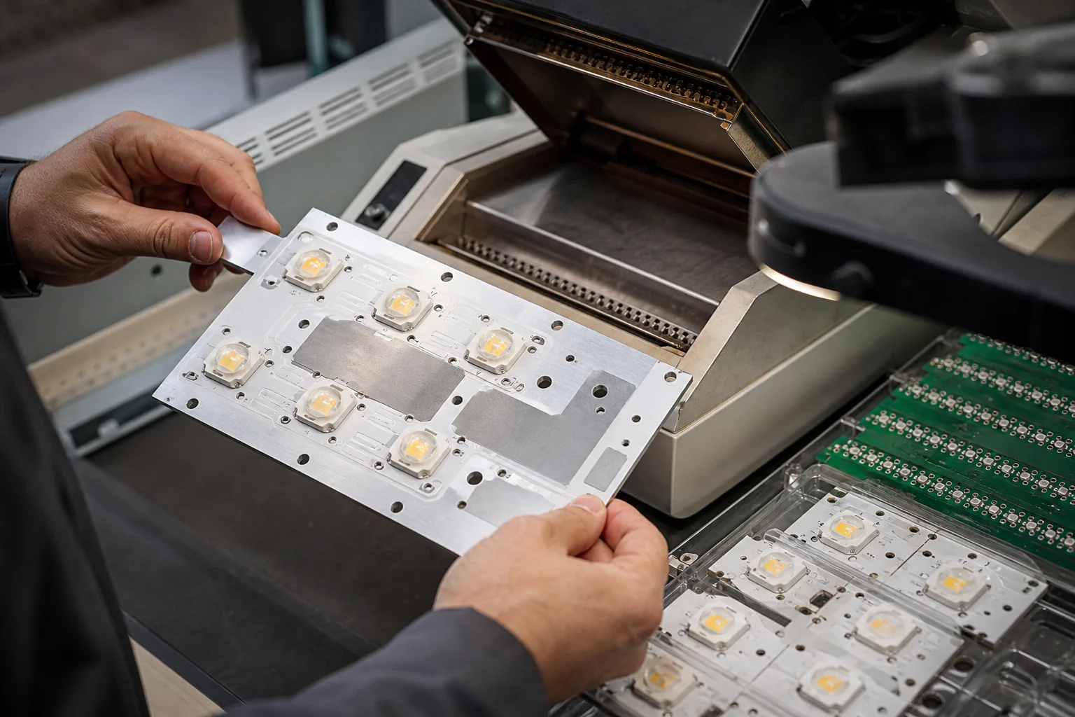
- Heat-damaged parts: forcing heat into temperature-sensitive plastic packages, connectors, or LEDs without shielding or preheat.
Failures should be diagnosed in sequence. First inspect the pad and lead geometry under magnification. Then check whether the flux was spent or contaminated. After that, look at thermal conditions such as copper balance, heat sinking, and whether adjacent components were disturbed during touch-up. This order prevents technicians from blaming solder alloy or tip temperature for what was actually a layout or rework-access problem.
Inspection Checkpoints Before the Board Leaves the Bench
Surface mount soldering should end with inspection, not with a joint that merely looks acceptable to the naked eye. At minimum, confirm full pad wetting, fillet shape where visible, lead alignment, no stray solder balls, no bridge between adjacent pins, and no lifted part edge on passives. If the board will later be coated, cleaned, or placed in a high-humidity environment, inspect flux residue and contamination risk as well. ReversePCB’s soldering flux guide and solder pad basics article both support this step because wetting quality and pad condition are connected.
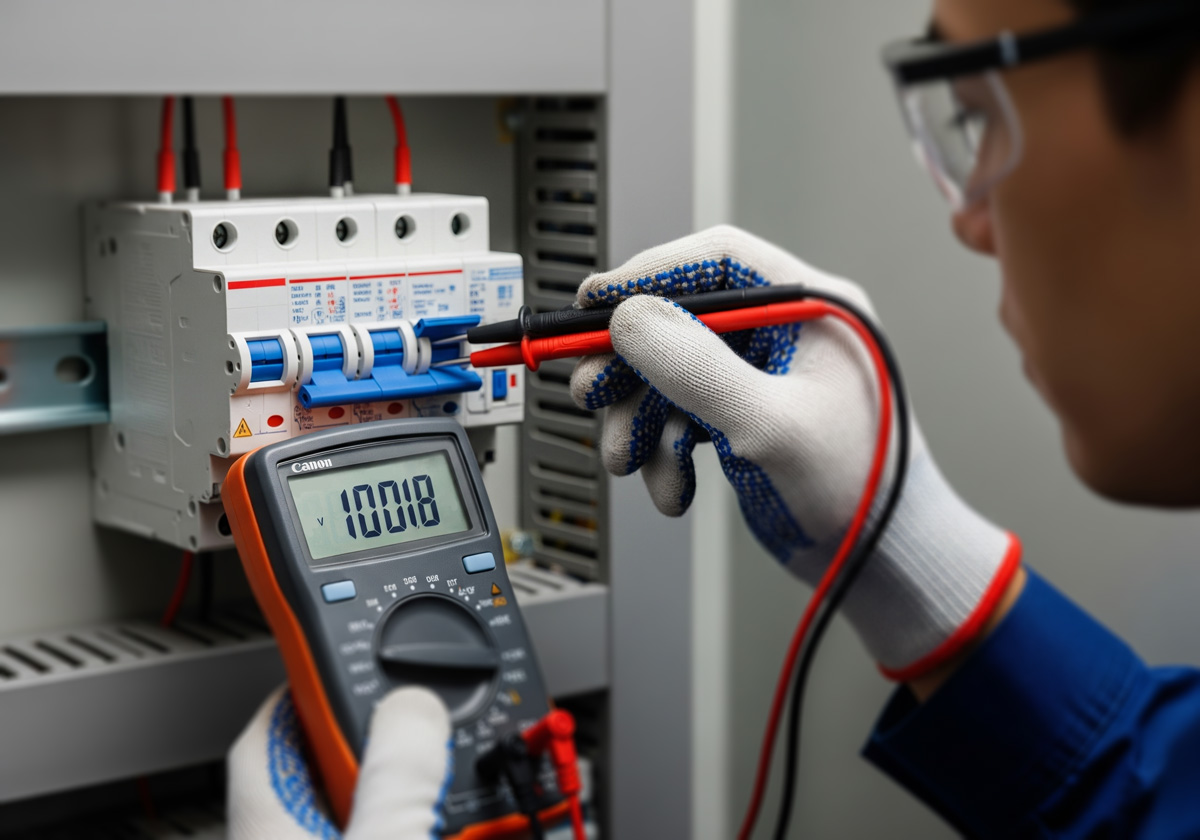
Electrical checks should match the board value. A quick continuity scan may be enough for simple prototypes, but fine-pitch power devices, analog front ends, and communication interfaces deserve resistance checks across suspect nets before first power. For reworked regulators or processors, it is often worth checking for shorts to ground and measuring rail impedance relative to a known-good board. That is faster than discovering a bridge during live power-up.
When Hand Soldering Stops Being the Best Option
There is a point where more bench skill does not offset process limits. If the part pitch is too fine for visual confirmation, the thermal pad requires controlled solder volume, nearby components are densely packed, or repeated rework is starting to weaken the laminate, move to a better process. That may mean hot-air rework with bottom-side preheat, a solder paste and hot-plate setup for prototypes, or full stencil-and-reflow assembly for repeat builds. Hand soldering remains valuable, but it is not the right answer to every SMT package.
That decision matters commercially as well. Rework-heavy assembly raises labor time, increases the chance of latent damage, and makes inspection less repeatable. If the same board will be built more than a few times, designing for assembly and choosing a controlled reflow path often costs less than repeated manual touch-up.
Final Takeaway
Good surface mount soldering is a controlled process, not a steady hand alone. Package choice, pad access, heat balance, flux use, and inspection discipline determine whether the joint survives beyond the bench. When the board and package are compatible with hand work, a technician can produce excellent results. When they are not, the better engineering move is to change the process before defects become expensive.
Can you hand solder surface mount components reliably?
Yes, but reliability depends on package type, pad access, and thermal balance. Passive chips, SOIC packages, and many leaded devices are practical by hand when flux, tip geometry, and inspection are controlled. Bottom-terminated parts such as QFNs are much less forgiving and often need paste, hot air, or reflow support.
What temperature should be used for surface mount soldering?
There is no single correct number for every board. The right iron setting depends on pad size, copper connection, tip shape, and how much heat the board is sinking away from the joint. If joints still refuse to wet, improve flux and preheat first instead of only turning the temperature higher.
Why do solder bridges keep appearing on fine-pitch SMT leads?
Bridges usually come from too much solder, poor lead alignment, or not enough flux during drag soldering. Using a small hoof or bevel tip with active flux often works better than trying to feed tiny amounts of solder pin by pin. Final cleanup with wick is normal and usually safer than repeated iron passes.
When should SMT assembly move from hand soldering to reflow or hot-air work?
Move to a controlled process when the package hides its terminals, the center pad needs accurate solder volume, nearby components leave little rework access, or repeated touch-up is starting to stress the laminate. At that point, process control matters more than bench speed.