LED PCB assembly looks simple from a distance: place the emitters, reflow the board, power it up, and check that the light turns on. In production, that mindset is expensive. High-power LED boards fail less often because a solder joint is visibly open and more often because heat was never managed correctly in the first place.
That is why the most useful LED assembly article for ReversePCB readers is not a generic definition of LED PCBs. It is a process guide for the points where thermal pads, board flatness, solder voiding, and profile control decide whether the board keeps its brightness and service life after the first few hundred hours.
LED Assembly Is Really a Thermal-Joint Problem
On a small logic board, a marginal solder joint may still pass early power-up. On an LED module, a weak thermal path shows up quickly as excess junction temperature, luminous decay, color shift, or uneven brightness from channel to channel. The electrical path and the thermal path are tied together.
That is especially true on metal-core boards and high-power LED modules, where the central thermal pad under the package does the hardest work. ReversePCB already explains what LED PCBs are. The assembly question is different: can the process create a repeatable thermal interface under every emitter, not just a board that lights up on day one?
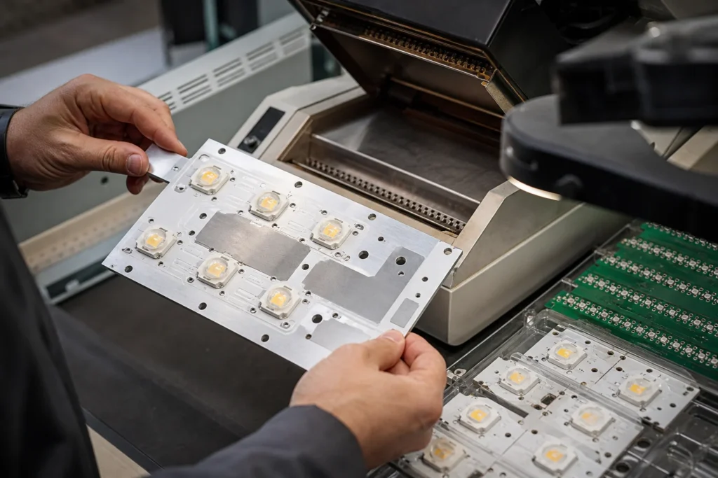
Why Thermal Pads Cannot Be Printed Like Ordinary Pads
The central thermal pad under a high-power LED package is usually the first place where assembly discipline separates a reliable build from a warranty problem. Too much paste can trap flux volatiles and leave large voids. Too little paste reduces wetting and creates poor thermal contact. A single open grid is rarely the right answer.
- Segment the paste pattern. Windowpane-style aperture strategies usually release paste more consistently than one large opening.
- Support the board correctly. Thin or unevenly supported boards print and reflow differently, especially when the LED package has a large thermal slug.
- Control paste height and slump. Thermal pads react strongly to excess volume because the gas has fewer paths to escape during reflow.
- Validate voiding expectations early. If thermal resistance is critical, the team should decide during pilot build how much voiding is acceptable instead of debating it after field failures.

Board Construction Changes the Reflow Window
LED boards are often built on aluminum-core substrates or unusually heavy copper constructions because heat removal matters. That changes the reflow problem. The board stores and redistributes heat differently from a standard FR4 logic board, so copying a legacy profile is risky.
- Metal-core boards heat unevenly if fixtures, conveyors, or support rails do not match the panel mass.
- Large LED packages can warp slightly during the hottest part of the profile, increasing the chance of weak wetting on one side of the thermal interface.
- Mixed thermal masses on the same board make it harder to optimize for both small passives and large emitter pads at once.
- Cooling rate matters because aggressive cooling can add stress to solder joints and lens-adjacent materials.
If the board also passes through curing, baking, or rework stages later, the team should think about the full thermal history, not just the first reflow. That is one reason oven choice and thermal-process control matter more on LED products than on many low-power digital boards.
Assembly Mistakes That Show Up as Optical Problems
LED boards often reveal assembly mistakes through optical symptoms rather than classic shorts-and-opens. A few patterns are worth watching:
- One emitter runs hotter than its neighbors. That usually points to thermal-pad inconsistency, not a mysterious LED bin issue.
- Color mismatch after burn-in. Early junction-temperature differences can age emitters unevenly and make matched bins drift apart.
- Lens contamination or flux residue. Poor paste or cleaning discipline can leave deposits that reduce light quality or complicate sealing.
- Mechanical bowing after reflow. Board stress can affect mounting pressure and long-term thermal interface behavior in the finished luminaire.
What a Good Pilot Build Should Prove
A strong pilot run for LED PCB assembly should prove more than basic electrical continuity. It should verify that thermal-pad printing is repeatable, that reflow settings control voiding acceptably, that the board remains flat enough for downstream assembly, and that brightness or color variation does not indicate hidden process drift.
In other words, the goal is not simply that the LED turned on. The goal is evidence that the board now has a stable thermal path that supports long operating life. That is the manufacturing standard worth writing for, especially when reliability claims or field replacement costs are real.
Why is LED PCB assembly more sensitive than a normal low-power board?
Because LED boards convert electrical error into heat, light-output drift, color inconsistency, and shortened service life. Thermal-pad quality matters as much as electrical continuity.
What is the most common process mistake on high-power LED boards?
Treating the central thermal pad like an ordinary pad is the most common mistake. Paste volume, voiding control, flatness, and wetting behavior all need tighter attention.
Can FR4 and metal-core LED boards use the same assembly rules?
Not reliably. Aluminum-core or other metal-core LED boards change heat flow, support needs, and reflow behavior, so stencil and profile decisions often need adjustment.
Why does solder voiding matter so much on LED assemblies?
Voids under the thermal pad raise junction temperature and reduce heat transfer, which can shorten LED life, shift color, or create brightness mismatch across the module.
When should LED boards get extra inspection after reflow?
Extra inspection is justified when the design uses large thermal pads, tight color-uniformity requirements, heavy aluminum-core boards, or service-life expectations that make hidden thermal-joint defects expensive.