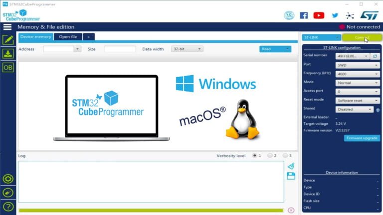
Introduction to STM32CubeProgrammer
STM32CubeProgrammer is a very powerful STM32 programming tool launched by STMicroelectronics. It highly integrates the functions of the following tools:
- STVP or STLinkUtility (JTAG/SWD programming tool)
- STMFlashLoaderDemo (UART programming tool)
- DfuSeDemo (USB burning tool)
- ST-LinkUpgrade (Stlink programmer firmware upgrade tool)
User Interface of STM32CubeProgrammer
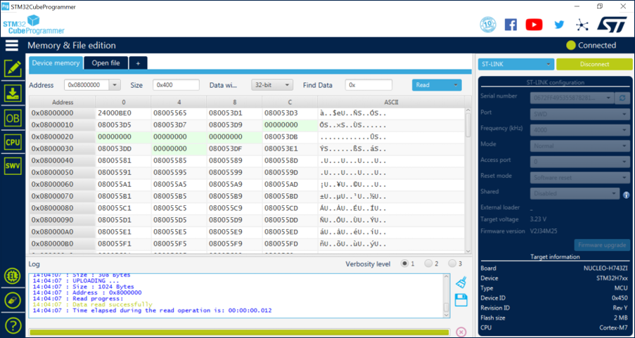
STM32CubeProgrammer provides both graphical and command line user interfaces. In addition, it also provides a C++ API, and users can integrate the functions of STM32CubeProgrammer into the PC applications they develop.
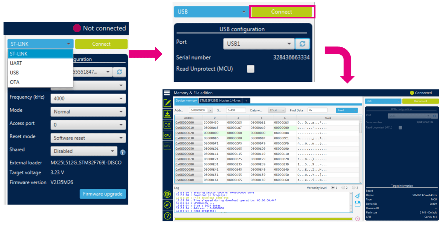
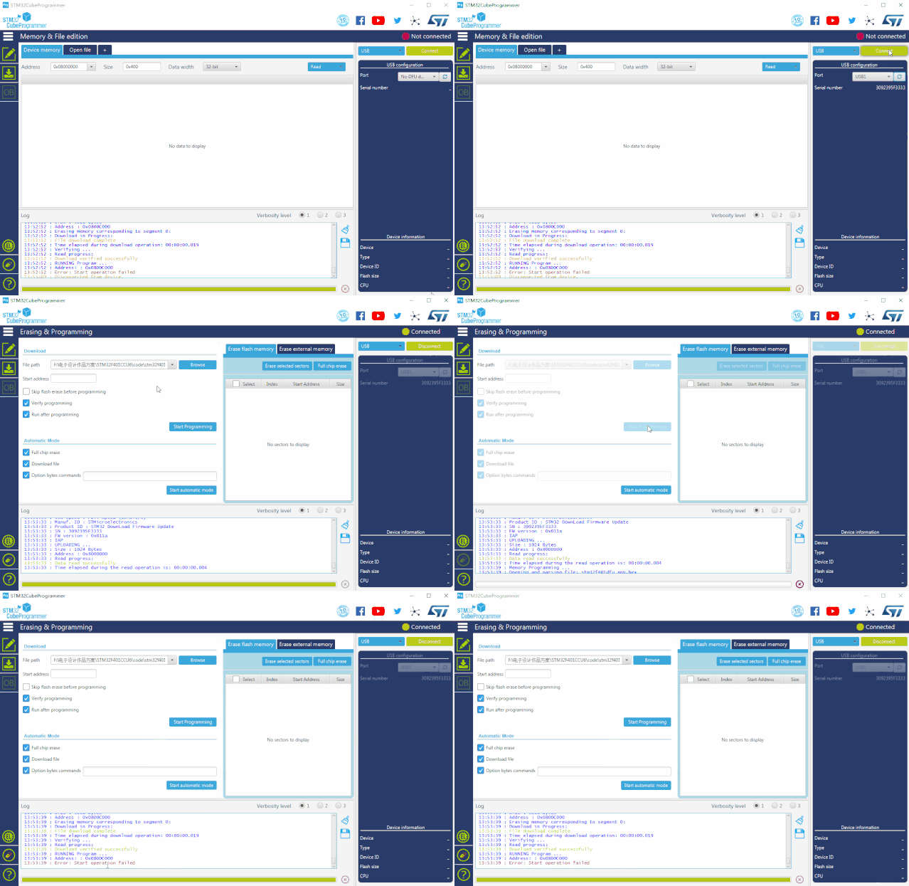
As shown in the figure above, in the configuration area on the right, users can choose to connect to the STM32 microcontroller through the STLink debugging interface, or communication interfaces such as USB and UART. After connecting to the STM32 microcontroller, you can see the current MCU model, version and Flash size in the “Device information” area. If an official ST development board is connected, the name of the development board will also be displayed.
Functions of STM32CubeProgrammer
STM32CubeProgrammer supports erasing and reading/writing the on-chip memory of STM32 MCUs through the STLink’s SWD/JTAG debugging interface or via communication interfaces such as UART, USB, I2C, SPI, and CAN, using the factory-programmed system bootloader stored inside the chip.
Here are the key functions of STM32CubeProgrammer:
Erasing and Programming
STM32CubeProgrammer supports sector-based erasing and full chip erasing of Flash memory. It can import various file formats for programming, including binary (.bin), elf (.elf, .axf, .out), hex (.hex), and Motorola S-record (.srec) files.
Erasing Operation
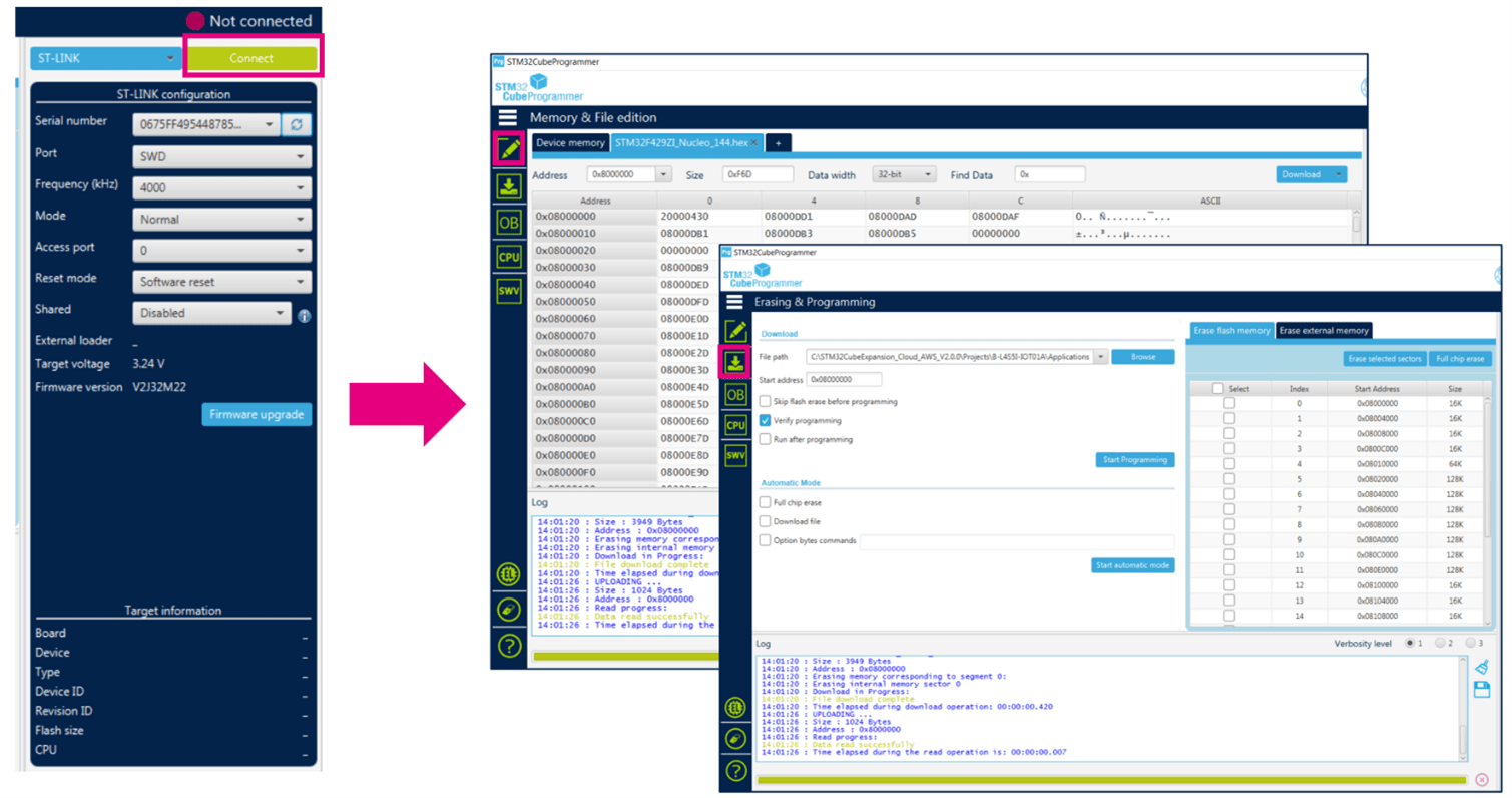
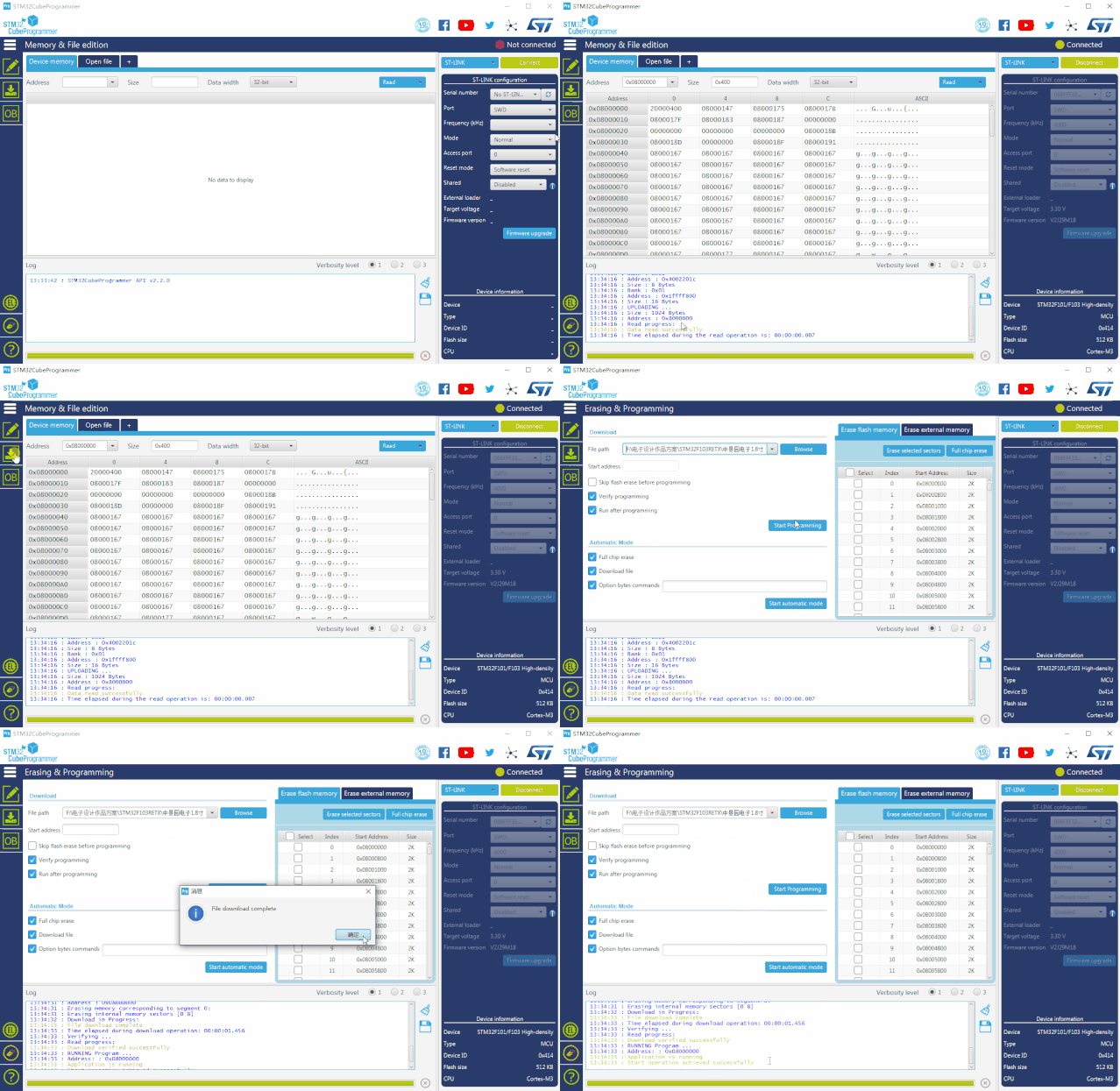
After establishing a connection with the target MCU through STLink, you can erase Flash sectors on the “Erasing & Programming” page by sector or perform a full chip erase by selecting the “Full chip erase” button.
Programming Operation
On the “Erasing & Programming” page, you can click the “Browse” button to import an executable file and then click “Start Programming” to initiate the programming process.
Alternatively, on the “Memory & File Edition” page, you can open the executable file you wish to program, and then click “Download” to start programming.
On the “Memory & File Edition” page under “Device Memory,” you can also read the values of the MCU memory at a specified address range and save the read content as binary (.bin), hex (.hex), or S-record (.srec) files using the “Save As” menu.
Apart from programming the entire executable file, you can directly modify the value at a specific address on the “Memory & File Edition” page under “Device Memory.” After pressing “Enter,” STM32CubeProg will automatically read, modify, erase, and write back. This method can be used for programming one-time programmable (OTP) bytes.
Option Byte Read/Write
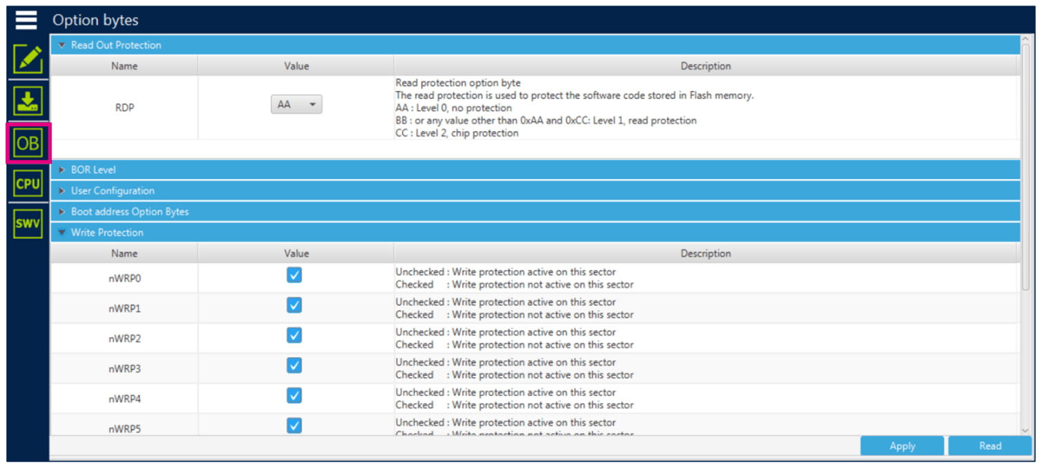
In the OB (Option Byte) page, you can view the current settings of the option bytes for the connected MCU. You can also modify the values of option bytes here. For detailed explanations of option bytes, please refer to the reference manual for the specific MCU.
"Two-in-One" Programming
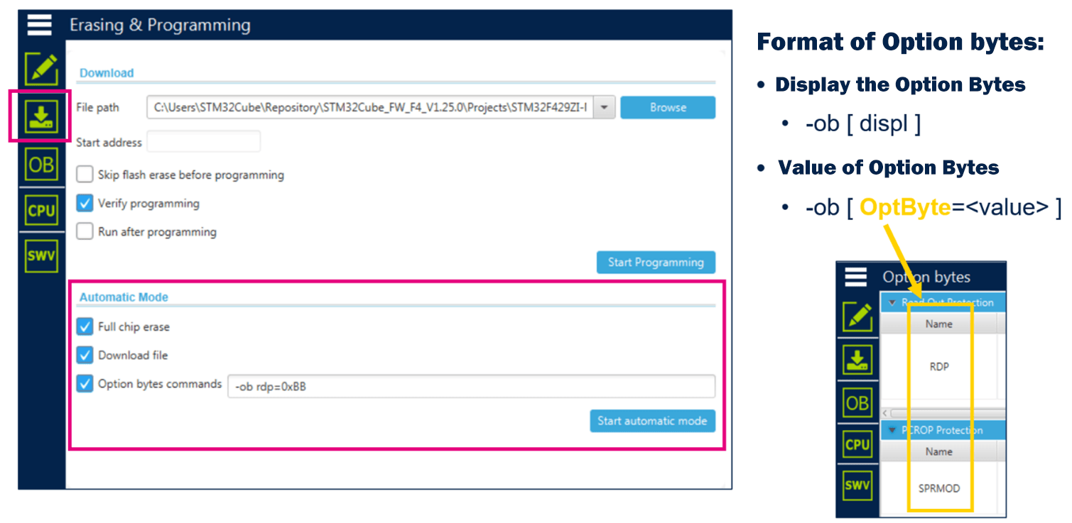
Using the “Two-in-One” programming mode on the “Erasing & Programming” page, you can program both the FLASH memory and option bytes in a single operation. Configuration of option bytes is done using the “STM32CubeProgrammer command-line” with the “-ob” command. For example, to set read protection to level 1 after programming FLASH, follow these steps:
- Set the path to the executable file to be downloaded.
- Check “Full chip erase” and “Download file” under “Automatic Mode.”
- In the “Option bytes commands” input box, enter “-ob rdp=0xBB.”
- Click “Start automatic mode,” and STM32CubeProgrammer will execute the specified operations in sequence, displaying the progress in the log window.
For details on the “-ob” command format, refer to section 3.2.15 of UM2237 (STM32CubeProgrammer Software Tool User Manual). The OptByte field definitions within the “-ob” command are not explained in UM2237, but you can find them by inspecting the “Option bytes” tab in the STM32CubeProgrammer graphical interface, as the definitions in the “-ob” command match those here. Alternatively, you can use the “-ob displ” command to display the current configuration of all option bytes, allowing you to understand the definitions of each OptByte field.
External Memory Read/Write
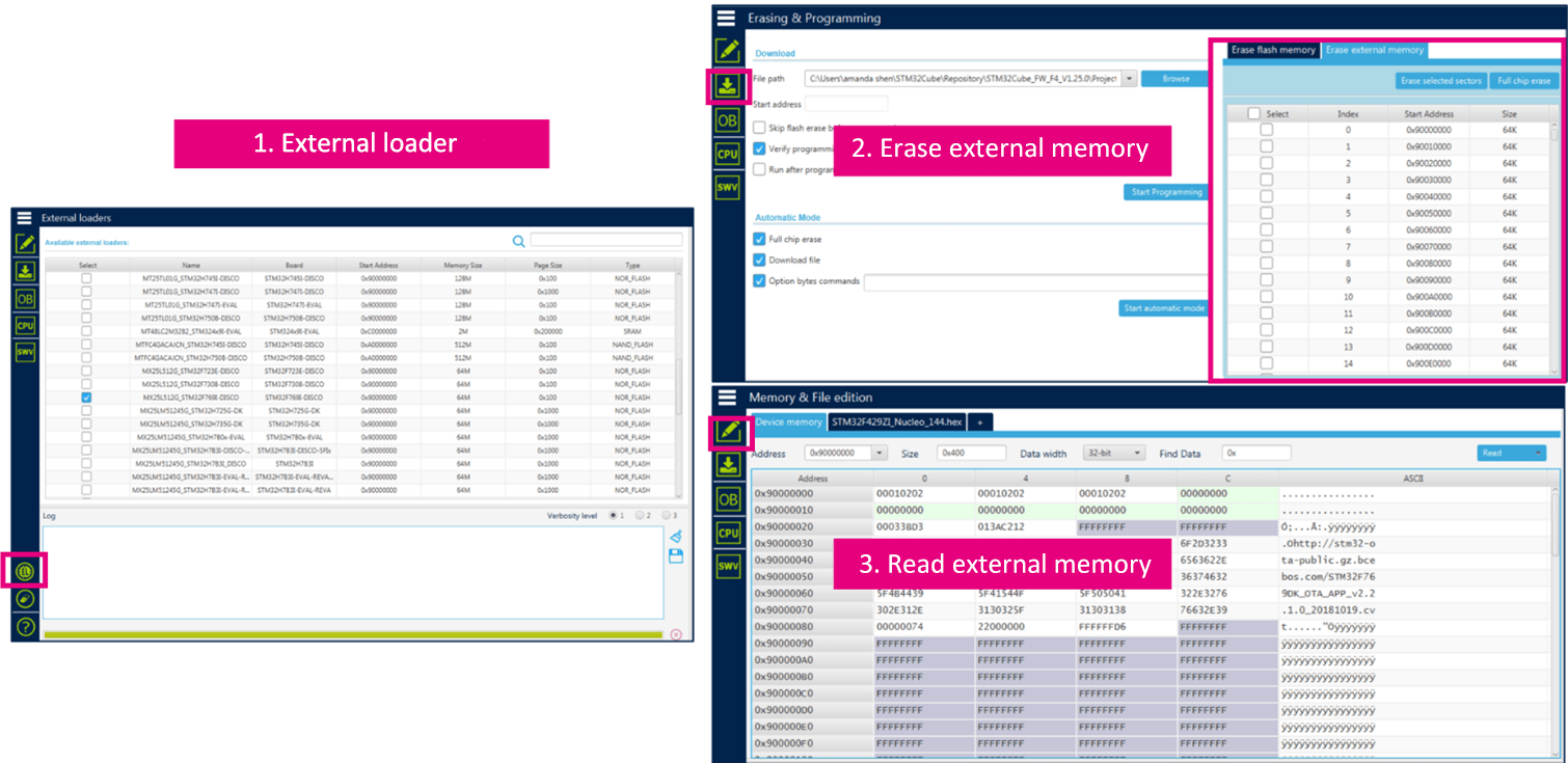
If you want to read/write to external memory connected to STM32 via interfaces like SPI, FMC, QSPI, you’ll need an external loader. CubeProgrammer provides default external loaders corresponding to the external memory integrated into STM32 development boards. If you are using a different memory model, you can create your own external loader files (*.stldr). Refer to section 2.3.3 of UM2237 for detailed instructions.
Before performing operations on external memory, you must select the corresponding external loader on the “External Loader” page. This external loader will be used in subsequent erase and programming operations on the external memory on the “Erasing & Programming” and “Memory & File Edition” pages.
Bootloader
Out of the box, STM32 MCUs come with an internal system memory that contains a bootloader, enabling updates to the on-chip Flash memory through interfaces like USART, USB, I2C, SPI, and CAN. The bootloader interface supported varies depending on the STM32 MCU model, and you can find specific information in application note AN2606. STLink v2 and STLink v3 provide bridge interfaces from USART, USB, I2C, SPI, and CAN communication protocols to USB, allowing STM32 MCUs to connect to a PC.
STM32CubeProgrammer provides a PC-side interface to perform erasing and programming of on-chip Flash memory via the bootloader. STLink v2 supports only USART and USB communication interfaces, while STLink v3 adds support for I2C, SPI, and CAN communication interfaces. ST previously offered two separate PC-side software tools: “STM32 Flash loader demonstrator” and “Dfuse Demo,” each supporting USART bootloader and USB DFU functionality. Now, you can use STM32CubeProgrammer, a single software tool, to support all these communication interfaces.
SWO Information Input Window
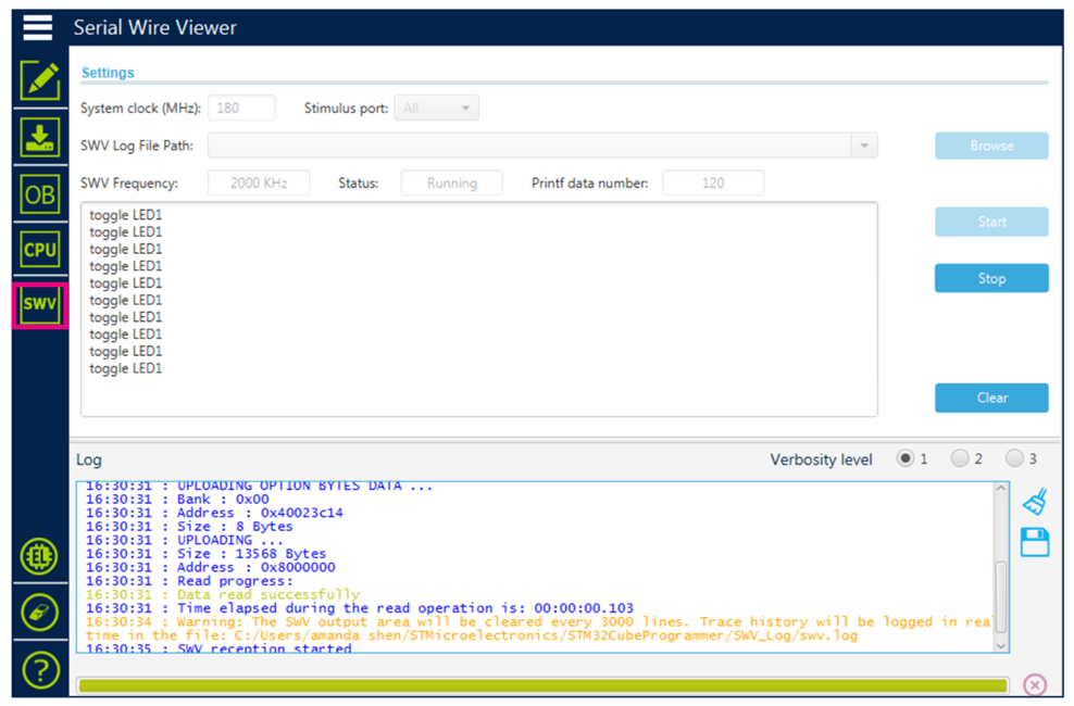
During development, it’s often necessary to output debugging information. One common method is redirecting printf output to a serial port, which consumes one serial port. Another method is redirecting printf output to the SWO (Serial Wire Output) pin via the SWD debugging interface, allowing debugging information to be sent through SWO. STM32CubeProgrammer’s SWV (Serial Wire Viewer) window can display debugging information sent via SWO and save all received information to a specified “.log” file.
Command-Line Interface
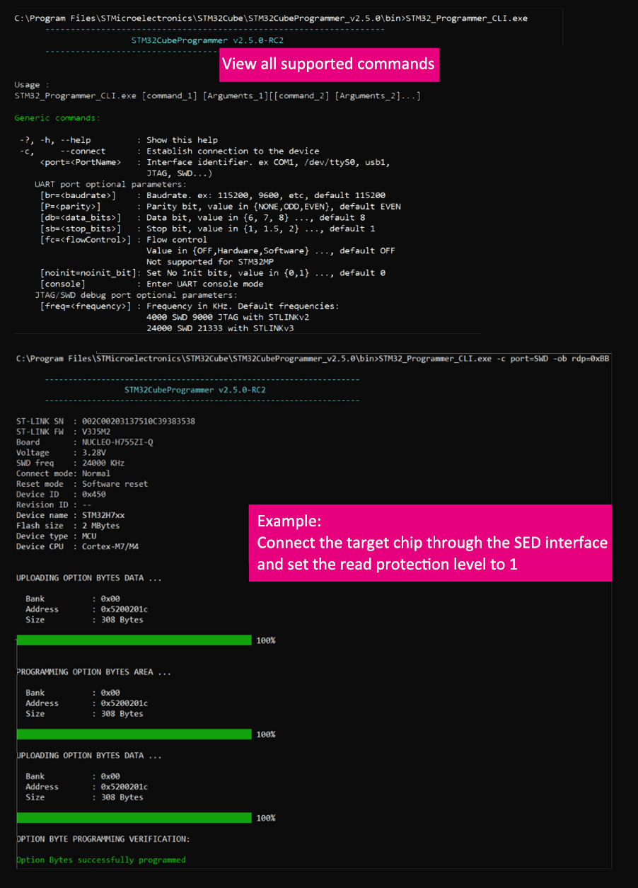
STM32CubeProgrammer provides a command-line interface that allows you to perform most of its functions by executing commands. The executable file “STM32_Programmer_CLI.exe” can be found in the “bin” folder of the STM32CubeProgrammer installation directory. Executing “STM32_Programmer_CLI.exe” will display a list of supported commands and their parameters.
The command-line interface also provides some functionalities not available in the graphical interface, such as creating trusted packages, secure programming, calculating CRC values, and more. For detailed instructions, refer to UM2237. The example in the figure demonstrates connecting to the target chip via the SWD interface and setting read protection level 1 using command-line instructions. The full command is “STM32_Programmer_CLI.exe -c port=SWD -ob rdp=0xBB.”
STLink Firmware Update
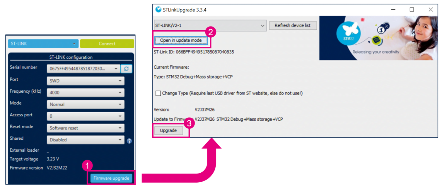
After connecting the STLink debugger to your computer, open STM32CubeProgrammer and refresh the STLink connection to view the current STLink firmware version. Click the “Firmware upgrade” button, and open the STLinkUpgrade tool to update the STLink firmware version.
How to Use STM32CubeProgrammer?
STM32CubeProg is a comprehensive programming tool that includes typical operations such as reading, writing (downloading/programming), erasing, and programming of option bytes.
STM32CubeProg Download
Official Website: https://www.st.com/en/development-tools/stm32cubeprog.html
Installation Environment
STM32CubeProg supports Windows, Linux, and macOS operating systems. Since it is based on JAVA, you need to install the Java Runtime Environment (JRE) on your computer. The installation process is shown in the image below (version 2.5.0b):
Connecting Chips and STM32CubeProg
When using STM32CubeProgrammer to connect to the target board via STLINK, there may be instances where the connection fails. This could be due to a low firmware version inside the STLINK. To address this, click the “Firmware upgrade” button to perform a firmware upgrade. During the upgrade process, you may need to plug and unplug multiple times. After the upgrade is complete, unplug and replug once for STM32CubeProgrammer to recognize the STLINK.
Chip Programming and Debugging
After completing program debugging, you need to program the chip with your code. Typically, you have three options:
- Use the JTAG/SWD debugging interface to program the chip, often requiring STLink Utility or STVP software.
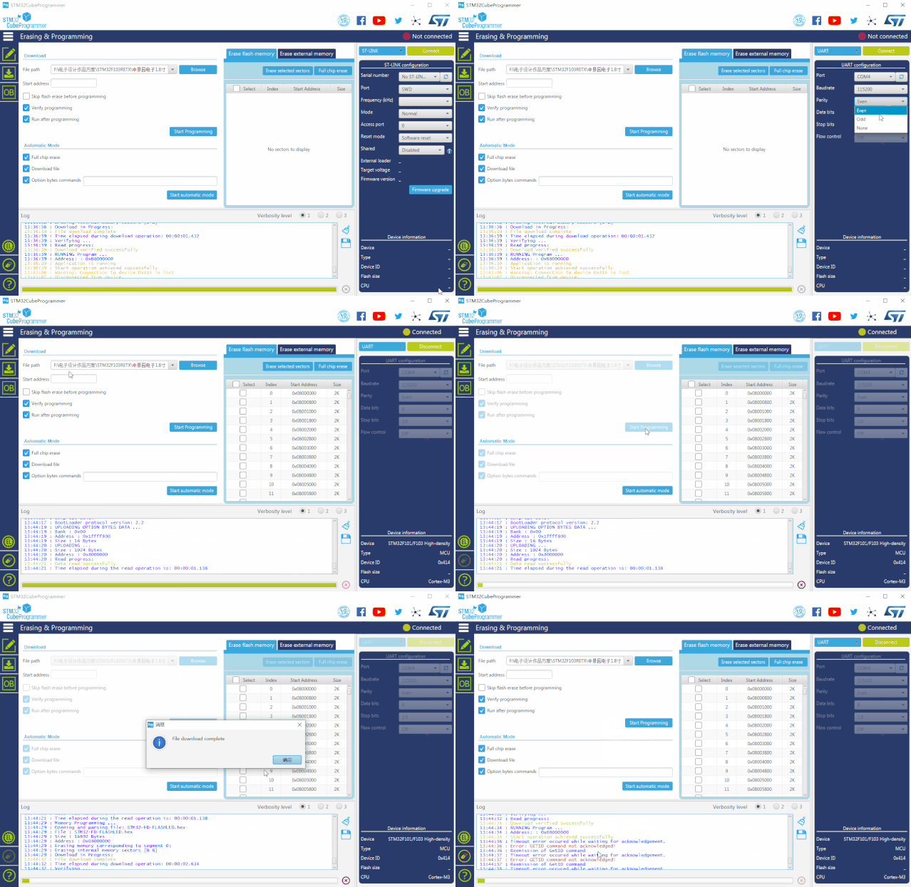
- Program the chip through the UART interface, using the STM32 Flash loader demonstrator software on the PC.
- Program the chip via the USB interface, utilizing the USB DfuSe software.

