A clock module is an electronic module, typically used to measure time and date, they usually include a crystal oscillator to generate an accurate time reference, and have some control circuitry for setting and adjusting the time.
In occasions with high clock requirements, DS1302 and ds3231 clock modules can meet the basic needs. Below I will introduce you the definition, pin diagram, parameters, functions, and programming of the ds3231 clock module.
What is the DS3231 RTC Module?
The DS3231 RTC Module is a popular Real-Time Clock (RTC) module that is commonly used in electronic projects. It is a small, low-cost device that provides accurate timekeeping and calendar functions. The DS3231 RTC Module is based on the DS3231 chip, which is an extremely accurate RTC with an integrated temperature-compensated crystal oscillator. It is capable of providing time and date information with an accuracy of up to ±2 ppm.
The DS3231 RTC Module is widely used in applications such as data logging, time-stamping, and alarm systems. It is also commonly used in electronic devices that require precise timekeeping, such as cameras, audio recorders, and industrial controllers. The module is easy to use and can be interfaced with microcontrollers such as Arduino and Raspberry Pi.
Overall, the DS3231 RTC Module is a reliable and accurate clock module that is widely used in various electronic projects.
DS3231 RTC Module Parameters
| Parameter | Value |
|---|---|
| Size | 38mm (length), 22mm (width), 14mm (height) |
| Weight | 8g |
| Working voltage | 3.3-5.5V |
| Clock accuracy | ±2ppm from 0°C to +40°C; ±3.5ppm from 40°C to +85°C |
| Calendar alarm clocks | 2 programmable |
| Square wave output | Yes |
| Real-time clock output | Seconds, minutes, hours, weekdays, dates, months and years |
| Leap year compensation | Up to 2100 |
| Temperature sensor | Built-in with ±3°C accuracy |
| Memory chip | AT24C32, 32K storage capacity, IIC bus interface |
| Memory chip features | Maximum transmission speed 400KHz, address can be modified |
| Battery backup | Yes, for continuous timing |
| Operating temperature | Commercial: 0°C to +70°C; Industrial: -40°C to +85°C |
| Power consumption | Low |
| Other features | Aging correction register, RST output, push button reset input |
| UL approved | Yes |
DS3231 Clock Chip Structure
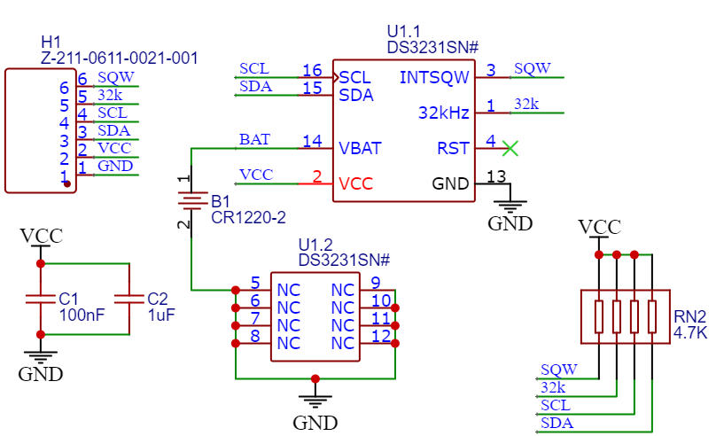
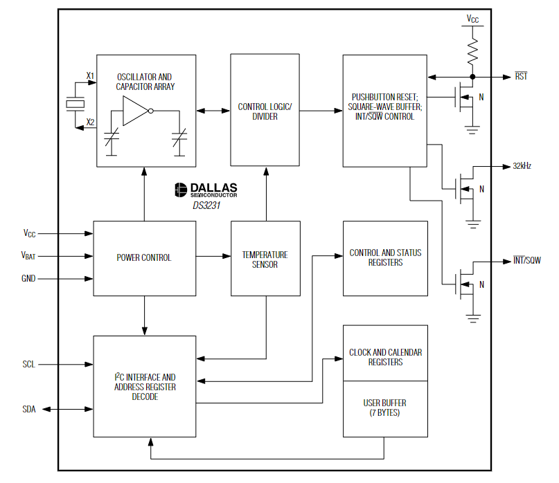
The DS3231 clock chip consists of eight modules, divided into four functional groups: TCXO, power control, reset button, and RTC.
DS3231 TCXO
The TCXO includes a temperature sensor, oscillator, and control logic. The controller reads the temperature sensor output on the chip, uses a look-up table to determine the required capacitance, adds aging correction from the AGE register, and then sets the capacitance selection register. New values, including changes to the AGE register, are only loaded when the temperature changes or when the user-initiated temperature conversion is completed. The temperature value is read at VCC power-up and then every 64 seconds.
DS3231 Power Control
The power control function is provided by the temperature-compensated voltage reference (VPF) and a comparator circuit that monitors the VCC level. When VCC is higher than VPF, the DS3231 is powered by VCC. When VCC is lower than VPF but higher than VBAT, the DS3231 is still powered by VCC. When VCC is lower than VPF and lower than VBAT, the DS3231 is powered by VBAT. To protect the battery, the oscillator does not start when VBAT is first applied to the device unless VCC is loaded or a valid I2C address is written to the device. The typical oscillator startup time is less than 1 second. After VCC power-up or a valid I2C address write, the device measures the temperature once and calibrates the oscillator using the calculated correction value after about 2 seconds. Once the oscillator is running, it remains in operation as long as the power (VCC or VBAT) is valid. The device measures the temperature and calibrates the oscillator frequency every 64 seconds.
DS3231 Reset Button
The DS3231 has a button switch function connected to the RST output pin. If the DS3231 is not in a reset cycle, it continuously monitors the falling edge of the RST signal. If an edge transition is detected, the DS3231 completes the switch debounce by pulling RST low. After the internal timer times out, the DS3231 continues to monitor the RST signal. If the signal remains at a low level, the DS3231 continues to monitor the signal line to detect a rising edge. Once the button is released, the DS3231 forces RST to a low level and maintains tRST. RST can also be used to indicate power failure alarms. When VCC is lower than VPF, an internal power failure alarm signal is generated, and RST is pulled low. If the oscillator does not work when VCC is loaded, tREC is skipped, and RST immediately becomes high.
DS3231 Clock and Calendar RTC
Clock and calendar information can be obtained by reading the appropriate register bytes. Clock and calendar data can be set or initialized by writing the appropriate register bytes. The contents of the clock and calendar registers are in binary-coded decimal (BCD) format. The DS3231 runs in 12-hour or 24-hour mode. The sixth bit of the hour register defines the 12- or 24-hour mode selection. When this bit is high, the 12-hour mode is selected. In the 12-hour mode, the fifth bit is the AM/PM indicator bit, which is logic high for PM.
DS3231 Internal Registers and Functions
DS3231 register addresses are 00h~12h, which are used to store seconds, minutes, hours, weeks, dates and alarm setting information respectively. During multi-byte access, if the address reaches 12h at the end of the RAM space, winding will occur. At this time Locate to the start position which is 00h unit.
The time and calendar information of DS3231 is set and initialized by reading the corresponding registers. The user auxiliary buffer is used to prevent possible errors when the internal registers are updated. When reading the time and calendar registers, the user buffer is under any START condition. Or synchronize with the internal register when the register pointer returns to zero.
The time information is read from these auxiliary registers, and the clock continues to run at this time, so that the re-reading of the registers can be avoided when the main register update occurs during the read operation. Taking the control register (address 0EH) as an example, it can control the real-time clock, alarm clock and square wave output.
DS3231 Pin Diagram
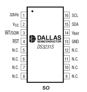
| Pin Name | Function |
|---|---|
| 32 kHz | 32 kHz frequency output |
| VCC | Used for the DC pin of the main power supply |
| /INT/SQW | Low-level active interrupt or square wave output |
| RST | Reset pin |
| N.C. | Indicates no connection; the external must be grounded |
| GND | Ground |
| VBAT | Backup power input |
| SDA | Serial data input and output |
| SCL | Serial clock input |
DS3231 Block Diagram
Program DS3231 RTC Module with Arduino Uno
Required Tools:
- Arduino Uno x1
- DS3231 RTC Module x1
- Jumper (DuPont line)
Wiring Instructions
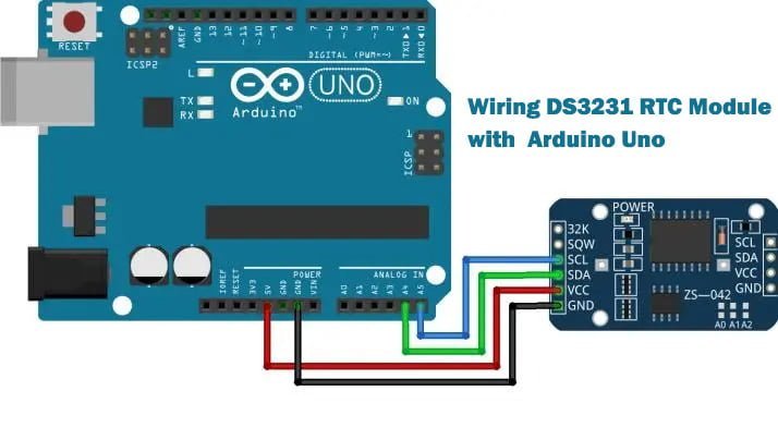
| Pin on DS3231 RTC Module | Pin on Arduino Uno |
|---|---|
| SCL | A5 |
| SDA | A4 |
| VCC | 5V |
| GND | GND |
Installing RTClib Library
The library used in this example is RTClib written by Adafruit, please install this library first.
Project – Load Libraries – Manage Libraries – Enter “RTClib” in the search box
Programming the DS3231
First, you need to load the RTClib library you just installed.
#include "RTClib.h"
After that, you can create a DS3231 instance named rtc, and you can call the function of RTC_DS3231
RTC_DS3231 rtc;
The functions used to set the time are rtc.adjust, for example:
rtc.adjust(DateTime(to_year, to_month, to_day, to_hours, to_minute, to_second));
It is used to rtc.now() obtain the time of DS3231, and the returned data is a DateTime type, which contains the data of the year, month, day, hour, minute, and second, for example:
					DateTime now = rtc.now();

  // Display the current time of DS3231 through the serial port output
  Serial.print(now.year(), DEC); // display the year in decimal
  Serial. print('/');
  Serial.print(now.month(), DEC);// Display the month in decimal
  Serial. print('/');
  Serial.print(now.day(), DEC);// Display the day in decimal
  Serial. print(" (");
  Serial.print(daysOfTheWeek[now.dayOfTheWeek()]);
  Serial. print(") ");
  Serial.print(now.hour(), DEC);// display in decimal
  Serial. print(':');
  Serial.print(now.minute(), DEC);// Display minutes in decimal
  Serial. print(':');
  Serial.print(now.second(), DEC);// Display seconds in decimal
  Serial. println();
Complete program code
					// by lingshunlab.com

// Load the library of DS3231
#include "RTClib.h"

// create rtc instance
RTC_DS3231 rtc;

String input_string; // Declare the variable input_string to store the data input by the serial port

// Declare a two-dimensional array variable daysOfTheWeek, which is used to match the corresponding week name through the index (index) of the array
char daysOfTheWeek[7][12] = {"Sunday",
                              "Monday",
                              "Tuesday",
                              "Wednesday",
                              "Thursday",
                              "Friday",
                              "Saturday"};

// get serial port data function
void GetSerialStuff(String& input_string) {
   String temp_string = ""; // Declare the variable temp_string to temporarily store the data input by the serial port
   while(Serial.available()) { // When the serial port has data, loop execution
     temp_string += (char)Serial.read(); // Combine the read serial data into the inStr variable one by one
     delay(2);
   }
   input_string = temp_string; // Assign the reference pointer variable to tempStr
}

void setup() {
   Serial.begin(9600);

   // Initialize rtc,
   if (! rtc.begin()) { // If initialization fails, then
     Serial.println("Couldn't find RTC");
     Serial. flush();
     abort(); // program stops
   }
}

void loop() {

   GetSerialStuff(input_string); // Get the data of the serial port
   if(input_string != "") { // If the serial port is not empty, then
     int to_year = input_string.substring(0, 4).toInt(); // Intercept year data from string and convert to int data type
     int to_month = input_string.substring(5, 7).toInt(); // Intercept the month data from the string and convert it to int data type
     int to_day = input_string.substring(8, 10).toInt(); // Intercept the day data from the string and convert it to int data type
     int to_hours = input_string.substring(11, 13).toInt(); // Intercept the hour data from the string and convert it to int data type
     int to_minute = input_string.substring(14, 16).toInt(); // Intercept minute data from the string and convert it to int data type
     int to_second = input_string.substring(17, 19).toInt(); // Intercept the second data from the string and convert it to int data type

     // Reset the time of the DS3231 module
     rtc.adjust(DateTime(to_year, to_month, to_day, to_hours, to_minute, to_second));
     delay(100);
   }

   // Get the time of DS3231
   DateTime now = rtc.now();

   // Display the current time of DS3231 through the serial port output
   Serial.print(now.year(), DEC); // display the year in decimal
   Serial. print('/');
   Serial.print(now.month(), DEC);// Display the month in decimal
   Serial. print('/');
   Serial.print(now.day(), DEC);// Display the day in decimal
   Serial. print(" (");
   Serial.print(daysOfTheWeek[now.dayOfTheWeek()]);
   Serial. print(") ");
   Serial.print(now.hour(), DEC);// display in decimal
   Serial. print(':');
   Serial.print(now.minute(), DEC);// Display minutes in decimal
   Serial. print(':');
   Serial.print(now.second(), DEC);// Display seconds in decimal
   Serial. println();

   // Display the temperature sensor data of DS3231 through the serial port output
   Serial. print("Temperature: ");
   Serial.print(rtc.getTemperature());
   Serial. println("C");

   delay(1000);
}
DS3231 Application
- Data acquisition systems
- Industrial control systems
- Battery backup
- Temperature monitoring
- Access control systems
- Medical devices


