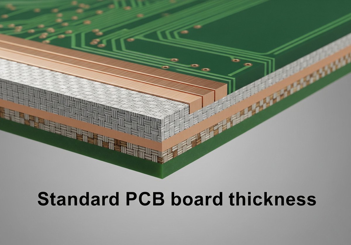
PCBs are an essential component of electronic devices that help reduce costs, increase the reliability of the devices, and reduce manufacturing time. Printed circuit boards with LEDs are commonly known as Light-emitting diode (LED) PCBs.
These are small computers built on single sheets of copper with copper tracks connecting different components that allows users to input data, store data, and display data in a visible format. This article covers everything you need to know about LED PCBs and their applications in different industries.
What is an LED PCB?
An LED PCB is a printed circuit board with a set of LEDs (light-emitting diodes) connected to its copper tracks. LED PCBs are the most commonly used boards in the world. They are widely used in commercial and industrial applications. Some common applications of LED PCBs include home appliances, office appliances, cars, and industrial machines. LED PCBs are usually rectangular and can be cut to any size as per the need of the application. The copper track on the PCB is connected to a set of terminals called pads. These pads are used to connect individual components like resistors, capacitors, and transistors to create the circuit.
Why Use LED Lights in PCB?
LED lights are becoming increasingly popular, and for good reason.
- More energy efficient
They are more energy efficient than traditional incandescent bulbs, and they last much longer. This means that you’ll save money on your energy bill and you won’t have to replace your bulbs as often. - Safe & non-tox
LED lights are also much cooler than incandescent bulbs, so they won’t heat up your room as much. And because they don’t contain any toxic materials, they are safer for the environment. - Longer life
LEDs are used in PCBs because they are efficient and easy to use. They are excellent components for communication, lighting, and signaling. They are reliable, and long-lasting compared to incandescent bulbs, halogen bulbs, and other light bulbs.
So if you’re looking for a more efficient, longer-lasting, and environmentally-friendly light bulb, LED is the way to go.
How does an LED PCB work?
LED Structure
The heart of the LED is a semiconductor wafer, and the entire wafer is encapsulated by epoxy resin. Semiconductor wafer is made up of two parts, and a part is P-type semiconductor, and hole occupies an leading position in it, and the other end is N-type semiconductor, is mainly electron here. But when these two semiconductors are connected, a “PN junction” is formed between them, which is equivalent to an electric field.
When the electrons come over, they will be repelled by the negative pole, that is, the N pole, and pushed to the positive pole, that is, the P area. In the P area, the electrons and holes recombine, and then energy will be emitted in the form of photons, which is what the LED emits light. principle. The color of light (wavelength of light) is determined by the material forming the PN junction.
Connecting the PCB and the LEDs
The connections between the pads of the PCB and the LEDs are made using wires (called conductors) made of a conductive metal such as copper or gold. The conductors are connected to the pads on the PCB and run to the terminals of the LED. The LEDs used in applications are of different colors, red, blue, yellow, green, and white. LED PCBs have a positive and a negative terminal that connects to the power supply. It is important to connect the positive and negative terminals of the LED PCB to the positive and negative terminals of the power supply. If the positive and negative terminals are connected incorrectly, the LED PCB will not light up.
LED Driver
The LED driver uses a small LED driver board from Microchip. It contains a 9V battery charger and a couple of LEDs connected to it. The LED driver board is connected to the power supply (2V/3A) via two 12V batteries (a pack of two).
The power supply is also used to control the LEDs. However, it’s not necessary for you to use this as an integrated circuit in your project because there are many different kinds of drivers available for different microcontroller platforms (e.g., PIC, Altera, etc.). You can use any voltage regulator or regulator with a small voltage drop on its output channel if you are using an integrated circuit from Microchip instead of an external power source.
Applications of LED PCBs
Communication and data transmission
LED PCBs are used in communication systems and data transmission systems. Transmission systems are the backbone of the internet, and communication systems are essential for maintaining health services. Communication systems are crucial during emergencies, and communication and data transmission systems can be designed using LED PCBs.
Light and illumination
LED PCBs are commonly used in illumination systems to provide light. They are used in street lights, and indoor lighting systems, and are also used in flashlights. They are also used in decorative lighting such as Christmas lights.
Display and signages
LED PCBs are an excellent choice for display systems and signage systems. They are used in billboards, and advertisements, and are also used in digital signs.
Home appliances
Home appliances like air conditioners, refrigerators, washing machines, and kitchen appliances use LED PCBs. They are also used in power outlets to indicate the presence of electricity and if the appliance is connected to the electricity.
Industrial machines
Industrial machines use LED PCBs for illumination, communication, and display. They are essential for controlling and monitoring different processes in the industry.
What should be Considered for buying LED PCB?
There’re many factors you should consider for buying led pcbs. For example, you need to know the Luminous Flux, color temperature, voltage. Below are details:
1. LED parameter
Performance characteristics generally include LED luminous flux parameters, LED dominant wavelength, LED rated voltage , LED color temperature parameters, etc.
Luminous Flux
The luminous flux Luminous Flux describes the total amount of light emitted by the light source. The larger the luminous flux of the light source, the more light is emitted, the higher the brightness is, and the higher the efficiency is at the same power. This luminous flux should focus on its corresponding test current. Note that the current here is the test current rather than the maximum current.
LED dominant wavelength
The main wavelength is used to represent the color of the LED, the unit is nm, mainly for colored LEDs, different main wavelengths have different colors, such as red for the main wavelength of 620-630nm, green for 520-540nm, etc.
LED color temperature
Color temperature is a parameter that characterizes the color of white light. Warm color temperature is 2700-3200K, neutral color temperature is 4000K-5000K, and cool white temperature is above 5600.
LED rated voltage
The rated voltage represents the voltage value of the LED at the rated current. Generally, the voltage of a single LED chip is 3-4V, and the chip voltage of the red LED will be relatively lower.
2. Characteristic Curves
The characteristic curve generally includes the spectral distribution diagram of the LED, the temperature-luminous flux curve, the current-luminous flux curve, and the current-voltage curve. The luminous flux output of the LED depends on both the current condition and temperature of the LED.

3. Mechanical Dimensions
The mechanical size is sometimes called the package size, which describes the size, positive and negative polarity direction and marking of the LED, and is mainly used for the layout application of the LED and the PCB board of the LED. The larger pad is the positive pole (Anode) of the LED. Viewed from the front, the direction marked with a triangle is the positive pole direction of the LED.

4. Others
LED specifications also contain some other content, such as numbering rules, welding guidelines, packaging conditions, etc. Among them, the soldering guide sets the temperature and time of the reflow soldering after the LED patch.
Conclusion
The benefits of using LED PCBs are many – they are an efficient source of light, provide good illumination, and consume less energy. They are used in communication and data transmission systems, and are an excellent choice for display and signages. Industrial machines use them for illumination, communication, and display. LED PCBs are a reliable circuit board that can be used for a wide range of applications.
Practical Notes for pcb led
For engineers researching pcb led, the most useful next step is to connect the concept to board-level constraints instead of treating it as an isolated definition. In a real PCB review, confirm the electrical limits, layout dependencies, measurement method, and failure symptoms before changing components or firmware.
- Design context: Review thermal paths, LED current, copper area, substrate material, and optical layout.
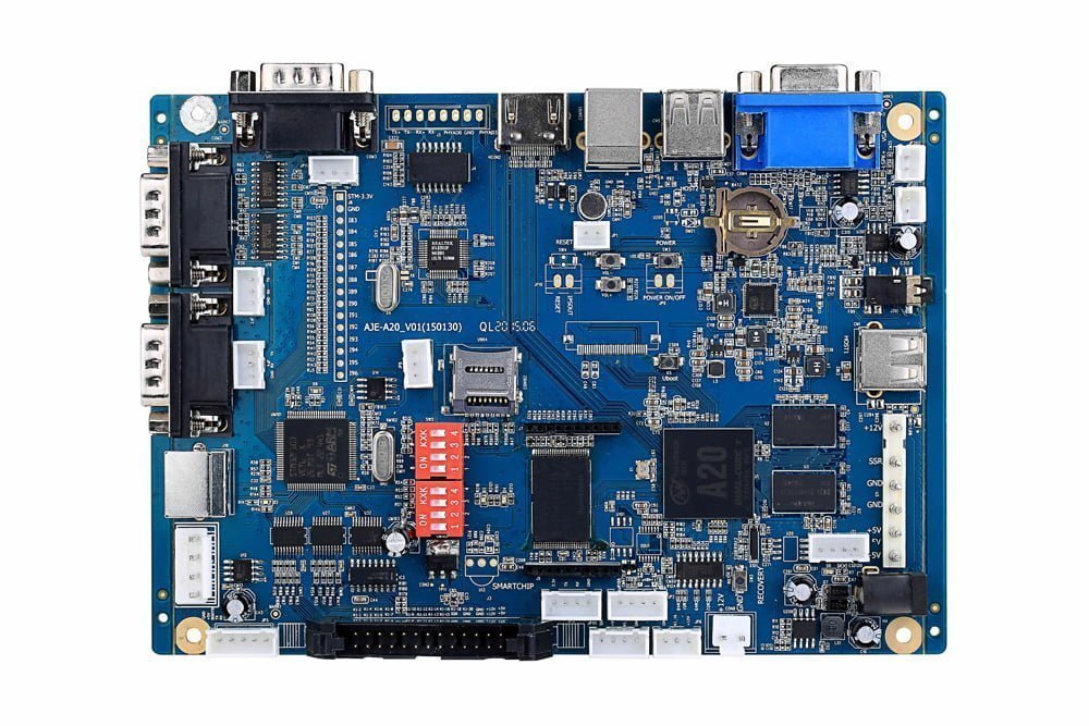
- Board inspection: Check component markings, connector orientation, reference designators, supply rails, and nearby protection components before making conclusions.
- Measurement plan: Use a current-limited supply first, then verify continuity, voltage rails, clock/reset behavior, and relevant signal waveforms.
- Documentation: Record photos, measured values, part numbers, and test conditions so later PCB reverse engineering or repair work can be repeated safely.
This checklist helps connect the search intent behind pcb led with practical electronics troubleshooting, PCB design review, and reverse engineering decisions.