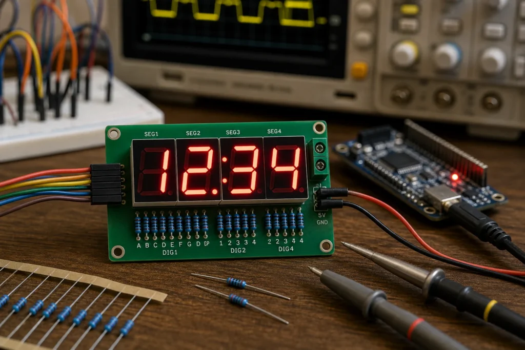
A seven segment indicator looks simple because the display geometry is simple. In practice, though, the design decisions around current limiting, common-anode versus common-cathode wiring, multiplex timing, and PCB layout decide whether the digits look crisp and balanced or end up dim, uneven, and harder to debug than they should be.
That is the useful answer behind both seven segment indicator and 7 segment indicator searches. Yes, it is a numeric display built from seven LED segments. But once the display moves from classroom symbol to real hardware, the driver strategy matters just as much as the digit shape.
What a Seven Segment Indicator Actually Is
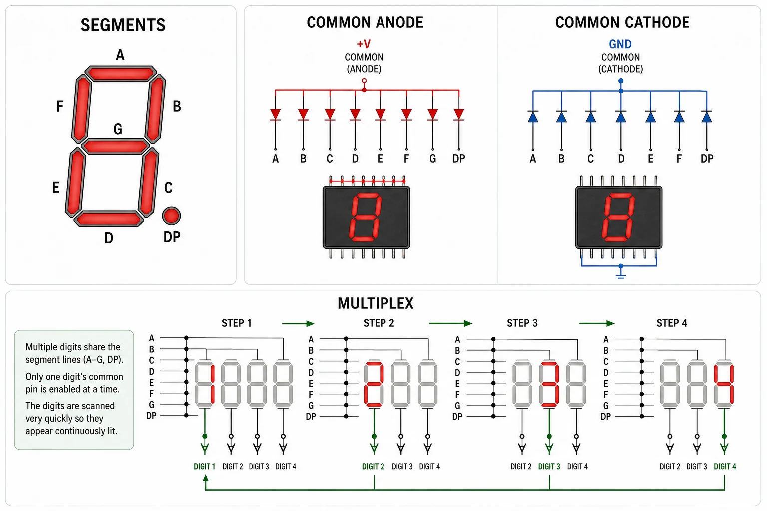
A seven-segment indicator uses seven individually controlled segments, usually labeled A through G, to display digits. Many modules also add a decimal point. By turning different segments on and off, the display can show numbers and a small set of letters.
From a PCB designer’s point of view, the more important distinction is electrical:
- Common cathode modules tie the LED cathodes together, so the driver usually sources current into each segment line.
- Common anode modules tie the anodes together, so the driver usually sinks current from each segment line.
If that common-node assumption is wrong, the schematic may still look plausible while the hardware refuses to light correctly.
Why Segment Current Is the First Design Check
The easiest mistake with a seven-segment indicator is to treat it like a logic symbol instead of an LED load. Every lit segment needs controlled current. If the resistor value is too low, brightness rises at the cost of heat and driver stress. If it is too high, the display becomes weak or inconsistent across supply conditions.
Each segment should usually have its own current-limiting path unless a very deliberate drive scheme says otherwise. Sharing one resistor across multiple segments may look cheaper, but the brightness changes with the numeral pattern because the current no longer stays predictable from segment to segment.
Multiplexing Saves Pins but Creates New Tradeoffs
Many boards multiplex multi-digit displays to reduce pin count. Instead of driving every segment of every digit continuously, the controller enables one digit at a time and refreshes them fast enough that the human eye sees a steady display.
That approach works well, but it changes the engineering problem:
- Peak current rises. Because each digit is on for only part of the cycle, the instantaneous drive current may need to be higher to maintain average brightness.
- Refresh timing matters. Poor scan timing causes flicker, ghosting, or one digit that looks weaker than the rest.
- Driver margins shrink. MCU pins are often not the right place to dump multiplex current directly, especially on larger or brighter displays.
This is where transistor arrays, dedicated display drivers, or careful sink/source budgeting become more important than the display symbol itself.
PCB Details That Affect Display Quality
Seven-segment indicators are not usually signal-integrity nightmares, but sloppy PCB choices still show up quickly. Long shared return paths can create uneven brightness. Weak decoupling near a multiplexed driver can let switching noise modulate the display. Poor connector or testpoint planning can also make bring-up annoying when one segment refuses to light and nobody can tell whether the fault is the module, the resistor, or the MCU pin mapping.
Thermal behavior also matters more than many low-power designs admit. A bright panel display in an enclosure can warm up enough to shift brightness or shorten LED life, especially if several digits are driven near their limit in continuous operation.
When a Dedicated Driver Is Better Than Direct MCU Control
For one small digit at modest current, direct MCU drive may be acceptable if the I/O budget and current ratings are honest. Once the design grows to multiple digits, higher brightness, or multiplexed operation, a dedicated driver usually makes the board easier to verify and easier to scale.
A display driver helps by standardizing current, simplifying timing, and reducing the risk that firmware changes quietly alter brightness behavior. It also removes some of the pin-current stress that otherwise lands on the MCU package and its ground return.
That same design discipline shows up in related tasks such as reading display schematics cleanly or choosing a resistor package that tolerates the real power and assembly context. The display itself is simple; the supporting circuit still deserves normal engineering care.
A Seven Segment Indicator Is Simple Only After the Driver Is Right
The display concept is easy to explain. The successful implementation is what takes judgment. Once you account for common-node polarity, per-segment current control, multiplex timing, driver headroom, and board-level debug access, a seven-segment indicator becomes much easier to integrate without the usual brightness and ghosting surprises.
FAQ
What is a seven segment indicator used for?
It is used to display digits, and sometimes a limited set of letters, in products such as counters, panel instruments, clocks, and simple embedded user interfaces.
What is the difference between common anode and common cathode seven-segment displays?
A common anode display ties the LED anodes together and usually needs segment-current sinking. A common cathode display ties the cathodes together and usually needs segment-current sourcing.
Why should each segment usually have its own resistor?
Separate resistors keep segment current more predictable. If several segments share one resistor, brightness changes with the number pattern because the current path is no longer balanced.
When is a dedicated seven-segment driver better than direct MCU drive?
It is usually better when the display has multiple digits, needs higher brightness, or uses multiplexing. A dedicated driver simplifies timing, current control, and MCU pin loading.