A PCBA functional test is the point where an assembled board stops being a visually acceptable product and starts proving that it can actually do the job it was built for. AOI, X-ray, and manual inspection can catch many assembly defects, but they cannot confirm that a power rail starts cleanly, a sensor interface responds, firmware boots, or a communication port survives a real transaction. Functional testing closes that gap.
For ReversePCB customers and electronics teams, the value is not just pass or fail. A well-designed test tells engineering which risks are controlled, tells production where repeat defects are forming, and gives purchasing or quality teams evidence before a batch leaves the factory. That is why a PCBA functional test should be treated as part of the manufacturing plan, not as a final-minute bench check.

What Functional Testing Should Prove
The first question is simple: what must the assembled board prove before it is safe to ship? For a power board, that may mean input protection, output voltage, ripple, load response, thermal behavior, and shutdown logic. For a controller board, it may mean oscillator startup, firmware programming, GPIO states, CAN, UART, USB, ADC readings, relay control, and sensor simulation. For an RF, motor, or high-current product, the test may need extra shielding, current limits, or fixture interlocks.
The mistake is trying to test everything with the same depth. A production functional test should focus on faults that are likely, expensive, or hard to catch earlier. Wrong component values, solder bridges, reversed diodes, marginal connectors, missing pull-ups, bad programming, and weak solder joints often show up through voltage, current, timing, or communication symptoms. Cosmetic differences or edge cases that belong in design validation should not slow every production unit unless they directly affect outgoing quality.
Build the Test Around Known Assembly Risks
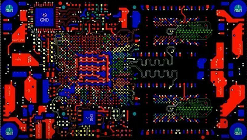
A useful PCBA functional test starts before the fixture is designed. Review the schematic, BOM, assembly notes, and known process risks. Dense QFN packages, fine-pitch connectors, polarized capacitors, crystals, boot-mode pins, and mixed-voltage interfaces deserve attention because small assembly errors can create confusing failures. If the board has already passed through a DFM review, use those manufacturing notes to decide which checkpoints deserve fixture coverage.
For example, an LED driver board may need a current-limited input, a simulated load, output voltage measurement, PWM dimming verification, and a temperature or fault signal check. A microcontroller board may need programming, boot confirmation, I/O toggling, ADC reference measurement, and serial communication. A communication gateway may need power-on current profiling, isolation checks, and protocol traffic. The best fixture is rarely the most complex one. It is the one that finds likely defects consistently without creating false rejects.
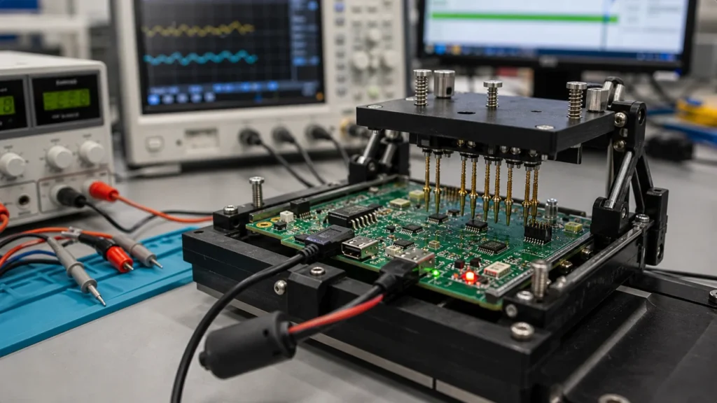
Fixture Design Matters as Much as Test Logic
The fixture is where many functional tests succeed or fail. Pogo pins need stable contact with test pads, enough compliance for board variation, and a layout that avoids shorting adjacent pads. The board should sit repeatably in the nest, with mechanical stops or guide pins that prevent a rushed operator from loading it at an angle. If the fixture presses on tall components or flexible areas, it may create intermittent failures that do not exist in the final product.
Test pads should be planned during PCB design, not added after the first build. Important rails, reset lines, programming pins, communication buses, and key outputs need accessible pads with enough clearance for reliable probes. When test access is poor, production teams often compensate with hand probing, temporary wires, or connector cycling. Those shortcuts increase handling damage and make the test harder to reproduce.
Typical Measurements in a PCBA Functional Test
Most production tests combine a few measurement types. Power checks confirm input current, standby current, output voltage, and short-circuit behavior. Digital checks confirm boot mode, firmware version, GPIO states, and communication response. Analog checks confirm sensor inputs, reference voltages, gain stages, or filtered outputs. Mechanical or user-interface checks may include buttons, LEDs, displays, relays, buzzers, connectors, and harness detection.
Limits should be realistic. A 5 V rail might not need to be rejected at 4.98 V if the circuit tolerance allows it, but a rail that ramps slowly or collapses under load may indicate a soldering, component, or regulator issue. Good limits come from design requirements, component tolerance, pilot-run data, and failure analysis. If limits are copied from a datasheet without considering the assembled circuit, the test may either miss defects or reject healthy boards.
Programming and Firmware Checks
Many boards cannot be functionally tested until firmware is loaded. That makes programming part of the test flow, not a separate afterthought. The fixture should confirm that the correct firmware version was written, the device ID or serial number was recorded, and the board can boot after power cycling. For microcontroller products, a simple?program success? message is not enough. The board should execute at least a minimal self-test or respond to a known command.
When a board uses locked firmware, secure boot, or calibrated parameters, the test station also needs traceability. Record the firmware version, test result, serial number, operator, fixture ID, and timestamp. That record becomes important when a customer reports a field issue and the team needs to know whether the board passed the intended production conditions.
Handling Failures Without Guesswork
A PCBA functional test should produce useful failure information, not just a red light. A board that fails because 3.3 V is missing needs a different repair path than a board that fails because CAN communication times out. Group failures by stage: fixture contact, power, programming, communication, analog reading, output drive, or final system response. This helps technicians decide whether to inspect solder joints, check component orientation, reprogram firmware, or escalate to engineering.
False failures deserve special attention. If many boards fail and pass on retest, the problem may be fixture wear, dirty pogo pins, poor alignment, unstable cables, or loose connectors. Treat the fixture as production equipment. Clean contacts, check pin spring force, verify calibration, and track fixture life. A weak fixture can make a good assembly line look bad.
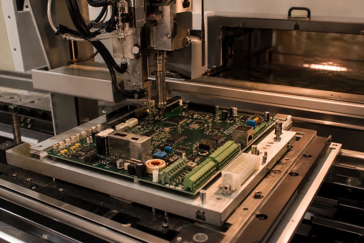
Where Functional Test Fits in the Assembly Flow
Functional testing usually comes after soldering, inspection, and any required cleaning or programming step. It should align with the broader PCB assembly flow rather than interrupt it. Some products need intermediate tests, such as in-circuit programming before enclosure assembly or high-current tests before conformal coating. Others can be tested once at the end. The correct placement depends on where defects become expensive to repair.
For prototypes or low-volume builds, a bench setup may be enough. For repeat production, a controlled fixture is usually worth the effort because it reduces operator variation and records results consistently. The goal is not to make the test station impressive. The goal is to ship boards with confidence and catch assembly faults while they are still cheap to fix.
A Practical Test Checklist
Before approving a functional test for production, check whether it covers these basics: safe power-up, current limits, required rails, firmware version, key inputs and outputs, communication ports, calibration or serial-number handling, fixture contact reliability, clear failure messages, and traceable records. Also confirm that operators know how to load the board, what to do with failed units, and when to stop the line if repeated failures appear.
A strong PCBA functional test is practical, repeatable, and tied to real product risk. It does not replace inspection, DFM, or design validation, but it gives the final assembled board a controlled chance to prove itself before shipment.
What is a PCBA functional test?
A PCBA functional test verifies that an assembled circuit board powers up, communicates, responds to inputs, drives outputs, and meets the required electrical behavior before shipment.
Is functional testing the same as AOI?
No. AOI checks visible assembly quality such as placement and solder appearance. Functional testing powers the board and confirms real circuit behavior, firmware response, interfaces, and measurements.
What does a PCBA test fixture usually include?
It may include pogo pins, a board nest, power supply connections, programming lines, measurement channels, simulated loads, communication adapters, safety interlocks, and software that records pass/fail data.
When should functional testing be planned?
Plan it during design and DFM review, because the PCB needs accessible test pads, stable fixture contact points, and clear requirements for power, firmware, communication, and output checks.