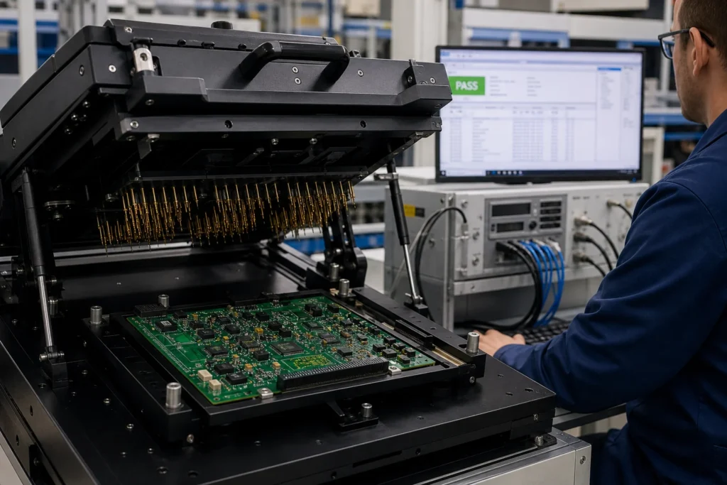
Automated test equipment sounds like an easy upgrade path in PCB assembly. Once the board is built, the story goes, the factory just places it into a fixture, pushes a button, and gets a fast pass-or-fail result. In practice, ATE only becomes useful when the team has already decided what the board must prove, which failure modes are worth catching at that stage, and how the fixture will reach the right nodes repeatably. Without that foundation, automation only accelerates a weak test concept.
That is why the most expensive mistake in PCBA testing is not always buying the wrong fixture. It is defining the test too late. If the design team has not agreed on power states, interfaces, safe access points, expected analog windows, programming dependencies, and acceptable takt time, the ATE project starts life as a moving target. The result is a fixture that exists, measurements that run, and coverage that still leaves the production team blind to the failures that actually matter.
The better approach is to define functional coverage first and let automation serve that plan. Once the board’s likely risks and must-catch behaviors are clear, ATE becomes easier to justify and easier to maintain.
What ATE is doing in a PCBA test flow
ATE in PCBA testing is best understood as a controlled measurement and decision system. It can power the board, stimulate interfaces, read responses, compare values against known limits, and store results consistently across many units. That can dramatically improve repeatability compared with ad hoc bench checks, especially once production volume rises. But ATE is not a replacement for thinking through the test architecture. It only executes what the team decided to measure.
On some assemblies, the automated step is narrow: a few rails, a short communication check, and one programmed functional pattern. On others, it becomes a substantial station with fixture interlocks, firmware loading, sensor simulation, analog capture, current monitoring, and serialized traceability. The correct scope depends on product risk, not on whether the word automation sounds impressive in a project review.
This is also why test planning belongs earlier in the design cycle. Engineers who can read electrical schematics with a manufacturing mindset tend to spot trouble early: hidden test access, rails that cannot be isolated, connectors that make fixture contact awkward, or interfaces that have not been given a practical way to prove functionality on the line.
Functional coverage has to come before fixture enthusiasm
Before a team chooses probes, fixture hardware, or software sequence, it should answer a simpler question: what faults must this station catch? Wrong polarity? Missing component? Bad solder on a regulator enable line? Incorrect firmware? Noisy analog gain? Unresponsive I2C device? If those risks are not ranked first, the fixture may end up optimizing convenience instead of yield protection.
Coverage planning also forces healthy tradeoffs. Some failures are better caught with upstream inspection, in-circuit checks, or programming verification rather than full functional automation. Other failures only appear when the board is powered in a realistic state. The right PCBA functional strategy usually mixes methods. ATE is one layer in that stack, not the whole answer.
When the coverage discussion happens early enough, design choices improve too. The board can expose better test points, isolate critical rails, route debug access sensibly, and reserve mechanical space for fixture contact. That connects directly to PCB schematic design decisions. Testability is cheaper when it is designed in than when it is forced in after assembly issues start appearing.
How to decide what the station should actually measure
Start with power integrity and safe bring-up
The first job of many automated stations is not complex logic. It is safe confirmation that the board powers correctly and does not present immediate risk. Rail shorts, overcurrent behavior, regulator sequencing, and standby consumption checks often belong near the front of the sequence because they protect the fixture and keep bad units from progressing into misleading downstream results.
Then prove the board’s essential functional paths
Once the board is safe to energize, the station should measure the behaviors that define product value. That may include clock presence, ADC response, programmed communication ports, sensor simulation, relay or driver actuation, or calibration entry points. The key is selectivity: measure what most clearly distinguishes a good board from a risky one. Do not pile in twenty low-value checks while leaving one critical failure mode weakly covered.
Keep pass-fail windows tied to engineering intent
Limit windows should come from how the product is supposed to behave, not from what one golden unit happened to produce on a quiet afternoon. If analog outputs, timings, or current levels matter, the test limits must be supported by design expectations, tolerance analysis, and realistic manufacturing spread. Otherwise the station becomes noisy, and operators stop trusting it.
Fixture design is where many ATE projects become fragile
A test fixture must make stable contact, protect the board, and support repeatability over many cycles. That sounds obvious until spring probes start wearing, connector access becomes inconsistent, or the clamping approach bends the board enough to introduce intermittent behavior. Engineers sometimes obsess over software first and discover later that the measurement system is only as good as the mechanical interface holding the PCBA.
Good fixture design starts by mapping the nodes that truly need access and confirming that the board layout supports them. This includes electrical access, mechanical tolerance, and operator loading behavior. If a crucial net is only reachable near a delicate component or under a cable path, the problem may belong to the board revision as much as to the fixture.

Fixture durability matters too. A station built for a pilot batch may fail quickly in recurring production if cleaning, alignment, wear-out, or pin replacement were never planned. The most reliable stations are rarely the most theatrical ones. They are the ones built around stable access, simple maintenance, and a sequence that proves the board without fighting the hardware every shift.
Common reasons automated PCBA tests disappoint
The line is measuring what is easy, not what is risky
It is common to see a station full of technically correct measurements that do little to protect yield. If the real field returns come from a marginal communication path, a weak power stage, or a programming dependency, the automation should aim there first. Test effort should follow failure economics.
Firmware, configuration, and hardware ownership are split badly
ATE almost always touches multiple disciplines. Hardware defines access and expected behavior. Firmware may control boot states or diagnostics. Manufacturing owns cycle time and repeatability. If those owners are not aligned, the station becomes hard to maintain because every change request crosses a boundary that was never clearly managed.
The design was never reviewed for testability
Boards are easier to test when key nets, connectors, indicators, and configuration states were considered during design. If that never happened, the station inherits awkward compromises. Engineers who understand the role of circuit board components in the signal path can usually identify which nodes deserve access long before the fixture build begins.
When ATE is worth the effort
ATE is most valuable when volume, failure cost, or traceability requirements make consistent board-level proof more important than bench flexibility. If the same product is built repeatedly, failure modes are understood, and the team can define clear limits around them, automation usually pays back. If the product is low volume, changes constantly, or still lacks agreement on what constitutes a valid board, manual or semi-automated functional checks may be the smarter short-term answer.
The right decision is rarely ideological. It is economic and technical at the same time. ATE should be adopted because it strengthens coverage at an acceptable lifecycle cost, not because it sounds like the mature option by default.
Conclusion
ATE in PCBA testing works only when it is built on a clear functional coverage plan. The fixture, sequence, and software are downstream from that decision. If the team first defines the failures that matter, the access the board must provide, and the limits the product must meet, automation becomes a powerful manufacturing tool.
If that groundwork is skipped, the station may still look capable while missing the faults that cost the most. In other words, ATE is not the strategy. It is the execution layer for a test strategy that should already be technically justified before the fixture is ever cut.
What does ATE mean in PCBA testing?
ATE means automated test equipment used to power, stimulate, measure, and judge PCB assemblies in a controlled production or engineering workflow. It is meant to improve repeatability and throughput, but its value depends on how well the test coverage was defined first.
Is ATE the same as a functional test on a PCBA?
Not exactly. Functional testing describes the goal of proving board behavior, while ATE describes the automated equipment and sequence used to perform some or all of that proof. ATE can deliver functional tests, but the terms are not interchangeable.
What should be decided before building a PCBA test fixture?
The team should decide which failure modes must be caught, which nodes need reliable access, what safe power-up behavior is required, which limits define pass and fail, and how much cycle time the line can afford. Without those answers, fixture design becomes guesswork.
When is automated testing worth it for PCB assembly?
It is worth it when product volume, failure cost, traceability demands, or repeated test steps justify the investment. The stronger the connection between automation and real coverage needs, the better the return on effort.