An SMT assembly line is easy to describe and surprisingly hard to balance. On paper the sequence looks clean: printing, inspection, placement, reflow, AOI, and test. On the factory floor, the real question is which station limits yield, which one limits takt time, and which one quietly creates defects that the next machine only exposes. That is why engineers who search for SMT assembly line guidance are usually not looking for a dictionary definition. They are trying to understand what equipment actually belongs in the line and what order of decisions prevents a fast line from becoming an unstable one.
The line only works as a system when each stage is sized around the same board family, the same package mix, and the same quality target. A printer that cannot control deposit repeatability will bury the line in placement and reflow noise. A placement platform that looks fast in a brochure may spend too much time on feeder changes or odd-form components. An oven with enough zones on paper may still create weak joints if the profile is built around an unrealistic thermal average. In other words, SMT line equipment should be selected by process fit, not by isolated machine specs.
If you need a broad refresher on terminology, ReversePCB already explains what SMT means in PCB assembly. This article moves one level deeper: what belongs in an SMT assembly line before speed becomes the goal, and how should the line be arranged when real production constraints matter?
The core stations in an SMT assembly line
A modern line usually begins with board loading and paste printing because print quality sets the ceiling for everything downstream. The stencil printer is not just an entry point. It is the station that determines solder volume consistency, bridging risk, and whether fine-pitch or bottom-terminated packages will have enough process margin to survive reflow. If the print is unstable, the rest of the line only becomes an expensive way to sort defects.
Most lines then place solder paste inspection immediately after printing when the product mix or quality target justifies it. SPI is valuable because it catches offset, insufficient volume, and aperture-specific transfer problems before components are committed to the board. That matters more than many teams admit, especially when paste behavior changes with stencil age, humidity control, or understencil cleaning discipline.
After print validation comes pick-and-place. In lower-mix lines one machine may be enough. In broader or higher-volume environments, it is common to separate chip shooting from flexible placement so the fast machine handles passives and the multi-function platform handles ICs, connectors, and odd packages. Reflow follows, then post-reflow AOI, and finally X-ray, ICT, or functional test depending on the package set and product risk.
What SMT line equipment actually determines throughput
Many equipment conversations over-focus on placement rate because placements per hour are easy to compare. That number matters, but it is rarely the whole answer. Throughput is usually constrained by the slowest stable station, and the slowest stable station is often the one that absorbs changeover friction, inspection holds, or thermal dwell. A line with an oversized placer and an undersized printer does not become fast. It becomes unbalanced.
Board mix changes the answer further. High-passive consumer boards may be placement-limited. Industrial control boards with mixed technologies may be changeover-limited. Dense power boards can become oven-limited if soak and peak behavior need more thermal care than the nominal conveyor speed suggests. A realistic SMT assembly line plan therefore starts with board family analysis: component count, smallest package, odd-form content, paste sensitivity, required traceability, and inspection depth.
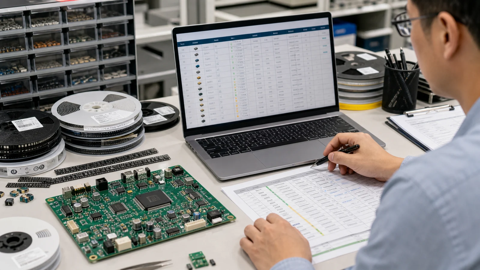
That is also why feeder strategy matters. Engineers sometimes size the line around machine head count and ignore how often feeder carts must be rebuilt. In medium-volume production, feeder setup discipline can matter as much as raw placement speed. An automated SMT line only stays automated when offline preparation, barcode control, and part verification are designed into the workflow instead of handled by operator memory.
Build the line around print quality before placement speed
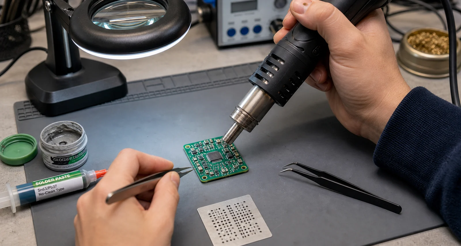
The printer deserves first-class attention because poor deposits amplify every downstream variable. Fine-pitch QFPs, QFNs, BTCs, and large thermal pads all rely on deposit geometry that survives release, placement pressure, and reflow collapse. When the printer and stencil strategy are weak, the line starts to chase symptoms: extra touch-up, unstable AOI calls, voiding complaints, and placement blame that does not belong to placement.
That is why the best SMT line equipment plan usually includes printer support functions as part of the line design rather than accessories. Understencil cleaning control, paste temperature discipline, board support tooling, and SPI feedback loops all belong in the throughput conversation. A printer that runs slowly but predictably will outperform a nominally faster setup that keeps feeding variation into the rest of the line.
Placement architecture should match package mix, not marketing speed
When one machine is enough
For simple boards, a single placement machine can be the most practical choice. The gain is lower capital complexity and easier maintenance. The tradeoff is that one machine must absorb every package type, feeder demand, and recovery event. That is acceptable when the board family is narrow and the takt requirement is moderate.
When dual-stage placement makes more sense
Once the line handles both large passive counts and more demanding IC or connector content, a split architecture often works better. A fast chip shooter handles the volume work, while a more flexible placer deals with orientation-sensitive and odd-form parts. This does more than increase nominal speed. It reduces compromise. The flexible machine can optimize accuracy without forcing the entire line to run at the slowest component type.
Do not forget setup and verification overhead
Even a well-matched placement pair will disappoint if feeder verification, reel change, and part traceability are weak. Many apparent placement problems are actually setup problems. Wrong feeder assignment, mislabeled alternates, and nozzle wear all create intermittent quality escapes that are costly to diagnose once the boards enter reflow.

Reflow, AOI, and test should be chosen as process gates, not afterthoughts
The reflow oven defines how much process margin the line really has. Zone count alone is not enough. The oven must support the thermal behavior of the actual assemblies, including heavy copper, heat-sinking shields, bottom-terminated packages, and mixed-mass layouts. If the board family is difficult, the line may need profiling discipline and conveyor strategy that are more important than a headline speed claim.
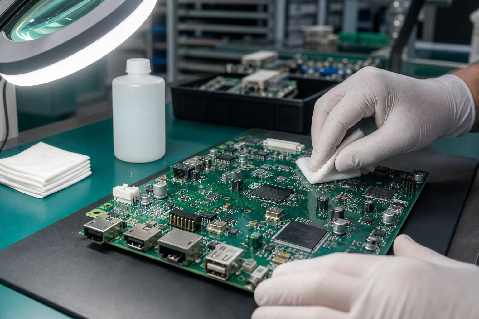
AOI should be sized around defect escape risk, not just customer expectation. On dense boards, AOI catches polarity issues, missing components, skew, and many solder-shape problems. It will not replace process understanding, but it can keep upstream drift from becoming downstream scrap. If the product uses BTCs or void-sensitive joints, X-ray may need to sit beside AOI in the release plan. If the failure risk is functional rather than purely visual, the line should be evaluated with end-of-line coverage in mind, not just image inspection.
What an automated SMT line still cannot automate away
Automation does not remove the need for DFM review, alternate-part control, stencil maintenance, or operator discipline. It mainly changes where the problems become visible. A line with barcode traceability and machine-to-machine handoff can still produce repeatable defects if the board support pins are wrong, the paste is aging on the printer, or a package library offset was approved too quickly.
Repair realities matter too. The more automated the line becomes, the more expensive uncontrolled rework tends to be. That is why a mature line strategy includes defect classification, repair authorization rules, and feedback into layout and sourcing. High automation without disciplined feedback often increases output volume faster than it improves quality.
How to plan SMT line equipment without overspending
Start with the boards, not the catalog. Group the intended assemblies by component density, package mix, expected lot size, and inspection depth. Map the real bottleneck candidates. Then decide which stations need margin and which only need adequacy. A factory that runs small industrial lots may gain more from fast changeover and feeder preparation than from maximum theoretical placements per hour. A factory running large passive-heavy consumer panels may make the opposite decision.
The best line plan is usually the one that keeps print quality stable, changeovers predictable, and thermal results repeatable. Once those are in place, higher placement speed becomes useful. Before they are in place, extra speed mostly pushes unstable work forward.
Conclusion
SMT assembly line equipment should be chosen as a connected production system. The printer sets the deposit quality, placement architecture sets flexibility and changeover behavior, and reflow plus inspection decide how much of that work survives into shippable boards. Throughput only becomes meaningful when those stages are balanced around the same product family.
If you are evaluating an SMT assembly line, begin with board mix, feeder strategy, process margin, and inspection coverage. That will tell you more about the right equipment sequence than a brochure speed chart ever will. The line that looks fastest on paper is often the one that spends the most time proving it is stable.
What equipment is normally included in an SMT assembly line?
A typical SMT assembly line includes board loading, stencil printing, optional solder paste inspection, pick-and-place, reflow, AOI, and downstream X-ray or electrical test when the product requires it. The exact sequence depends on board complexity and inspection risk.
What usually limits SMT line throughput?
Throughput is often limited by the slowest stable process step, not the fastest advertised machine. In many lines that means print consistency, changeover time, feeder preparation, or oven dwell requirements rather than placement head speed alone.
When should one SMT line use more than one placement machine?
A split placement setup makes sense when the board mix combines large passive counts with more demanding IC, connector, or odd-form content. One machine can then optimize speed while the other focuses on flexibility and accuracy.
Does an automated SMT line remove the need for process engineering?
No. Automation improves repeatability, but stencil design, paste control, board support, library accuracy, thermal profiling, traceability, and repair rules still determine whether the line stays stable and cost-effective.