PCB Radar: Design Basics for Radar Circuit Boards
PCB radar usually refers to a printed circuit board designed for radar sensing, RF signal transmission, or radar signal processing. In modern electronics, radar is no longer limited to large military or aviation systems. It also appears in automotive sensors, industrial distance measurement, smart home presence detection, robotics, drones, and IoT devices.

The PCB matters because radar circuits often work at high frequencies. At those frequencies, traces, copper pours, dielectric material, connector placement, and antenna layout can affect performance. A radar PCB is not just a carrier for components; it becomes part of the RF system.
This guide explains what PCB radar means, how radar circuit boards work, which materials and layout rules matter, and what to check before designing or manufacturing one.
What Does PCB Radar Mean?
PCB radar means a radar-related circuit built on or integrated with a printed circuit board. The board may include the radar transceiver, antenna structure, filters, power circuits, digital processing, connectors, and sensor interface circuits.
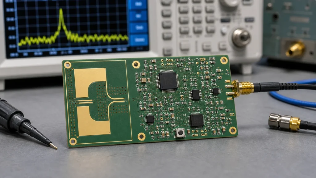
Some radar PCBs use a separate antenna connected by coaxial cable or RF connector. Others use an antenna printed directly on the PCB, such as a microstrip patch antenna or antenna array. In compact products, the antenna, RF front end, and processor may all sit on one small board.
The term can also describe a radar module PCB. For example, a 24 GHz or 60 GHz radar sensor module may be mounted on a larger product board and used for motion detection, distance measurement, or occupancy sensing.
How a Radar PCB Works
A radar PCB helps generate, transmit, receive, and process radio frequency signals. The radar circuit sends out an RF signal, receives reflections from nearby objects, and uses those reflections to estimate distance, speed, direction, or presence.
In a simple radar module, the RF section creates the signal and feeds it to an antenna. The same board may include a receiving path, mixer, amplifier, filter, analog-to-digital converter, microcontroller, or digital signal processor.
The layout is critical because radar signals can be very sensitive to loss, noise, and impedance changes. A poorly routed RF trace or badly designed antenna area can reduce range, distort the signal, or make the sensor unstable.
Common Applications of Radar PCBs
Radar PCBs are used wherever compact electronic systems need non-contact sensing. Automotive radar is one of the best-known uses, especially for blind-spot detection, adaptive cruise control, parking assistance, and in-cabin sensing.
Industrial systems use radar for distance measurement, level sensing, object detection, and safety monitoring. Radar can work in dust, fog, vapor, or low-light conditions where optical sensors may struggle.
Consumer and smart building devices may use radar PCBs for presence detection, gesture sensing, occupancy monitoring, and automatic lighting control. Small radar modules are also common in robotics, drones, and security devices.
Each application has different design priorities. Automotive radar often needs high reliability and strict material control. A smart home sensor may focus more on cost, size, and low power consumption.
Key Parts of a Radar PCB
A radar PCB may include an RF transceiver, antenna, filters, power management, clock circuits, shielding, control circuitry, and digital processing. The exact parts depend on whether the board is a complete radar module or only one part of a larger radar system.
The antenna is one of the most important parts. It may be a printed PCB antenna, patch antenna, antenna array, or external antenna connected through RF hardware.
The RF front end handles high-frequency transmission and reception. It may include amplifiers, mixers, filters, impedance matching networks, and transmission lines.
The processing section handles control and data. This may be a microcontroller, DSP, FPGA, or radar sensor IC with built-in processing.
The power section must be quiet. Noise from regulators or switching supplies can couple into sensitive RF and analog circuits if the layout is not planned carefully.
Radar PCB Materials
Radar PCB materials are chosen for stable high-frequency behavior. Standard FR-4 may work for some lower-frequency or non-critical circuits, but many radar designs need low-loss RF laminates.
For high-frequency radar, the dielectric constant and loss tangent of the material become important. If the material varies too much, the antenna and transmission line performance can shift.
Common RF PCB material families include PTFE-based laminates, hydrocarbon ceramic materials, and other low-loss substrates. Designers may also use hybrid stackups, with RF layers made from high-frequency material and digital layers made from more common PCB material.
Material choice affects signal loss, impedance control, cost, manufacturability, and thermal stability. It should be selected early, not after the layout is already finished.
PCB Radar Layout Guidelines
Radar PCB layout should start with controlled impedance, clean return paths, and careful antenna placement. At radar frequencies, small layout mistakes can become real performance problems.
Before routing the RF section, review practical PCB layout guidelines and apply them with stricter attention to impedance, grounding, and antenna clearance.
Keep RF traces short and direct. Use the correct transmission line structure, such as microstrip or stripline, based on the stackup. Avoid sharp corners, unnecessary vias, and uncontrolled trace width changes in RF paths.
Protect the antenna area. Printed antennas need clear keepout zones, stable ground references, and enough distance from metal parts, connectors, screws, batteries, and displays.
Separate noisy circuits from RF sections. Switching regulators, clocks, high-speed digital buses, and motors can inject noise. Use grounding, shielding, filtering, and placement strategy to reduce coupling.
Plan test access carefully. Once RF shields are installed, some points may be hard to probe. Include test points and calibration access where they make sense.
Manufacturing Challenges
Radar PCBs can be harder to manufacture than ordinary digital boards because they often require tight impedance control, stable materials, fine geometry, and careful layer registration.
The PCB fabricator needs to understand the stackup, copper thickness, dielectric material, impedance targets, and tolerance requirements. A small change in material or copper roughness can affect high-frequency performance.
Solder mask can also matter near antennas and RF traces. In some designs, solder mask is removed from critical RF areas to keep performance predictable.
Assembly also needs care. RF connectors, shields, fine-pitch radar ICs, and thermal pads must be placed and soldered consistently. Poor assembly can create intermittent or hard-to-debug radar problems.
Common PCB Radar Design Mistakes
One common mistake is treating a radar PCB like a normal low-speed control board. RF traces, antenna structures, and return paths need more attention than ordinary GPIO or power routing.
Another mistake is changing materials late in the project. If the antenna and transmission lines were designed for one dielectric material, switching to another material can shift the impedance and frequency behavior.
Placing metal too close to the antenna is also risky. Enclosures, screws, shields, cables, and batteries can detune antennas or block radiation.
Ignoring power noise can cause unstable readings. Radar sensors often need clean supplies, good decoupling, and careful regulator placement.
Finally, skipping prototype testing is dangerous. Simulation helps, but radar performance should still be checked with real boards, real enclosures, and realistic mounting conditions.
Conclusion
PCB radar design combines circuit board layout, RF design, materials engineering, and practical manufacturing control. A good radar PCB needs the right substrate, controlled impedance, clean RF routing, careful antenna placement, quiet power, and a fabricator that can hold the required tolerances. If you are starting a radar PCB project, begin with the radar frequency, antenna plan, stackup, and material choice before routing the rest of the board. For custom radar hardware, a PCB design service can help review RF layout, materials, and manufacturing constraints early.
What makes radar PCB layout different from ordinary digital layout?
Radar PCB layout is sensitive to impedance, RF return paths, antenna geometry, via fences, shielding, and material loss. Small layout changes can affect range, noise, and emissions.
Why does a 50 ohm trace matter in radar circuits?
Many RF components and test instruments expect a 50 ohm environment. A mismatch can create reflections, reduce transferred power, and distort measurements.
Should radar antenna areas have a keepout?
Yes. Metal, copper pours, tall components, and enclosure parts near the antenna can detune or block the RF field. Follow the module or antenna layout guidance closely.


