What are STM8 Nucleo Boards?
STM8 Nucleo Boards refer to a range of development boards designed by STMicroelectronics specifically for their STM8 microcontrollers. These boards serve as a convenient and flexible platform for building and testing applications based on the STM8 microcontroller family. With a variety of features and connectivity options, STM8 Nucleo Boards provide developers with a suitable environment to prototype their projects and evaluate the performance of the STM8 microcontrollers. These boards typically come equipped with a debugger/programmer, GPIO pins, UART, I2C, and SPI interfaces, allowing developers to easily connect and interface with various peripherals and sensors. STM8 Nucleo Boards are widely used in the electronics industry for their ease of use and compatibility with the STM8 ecosystem.
NUCLEO-8L152R8 and NUCLEO-8S208RB
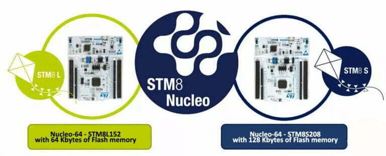
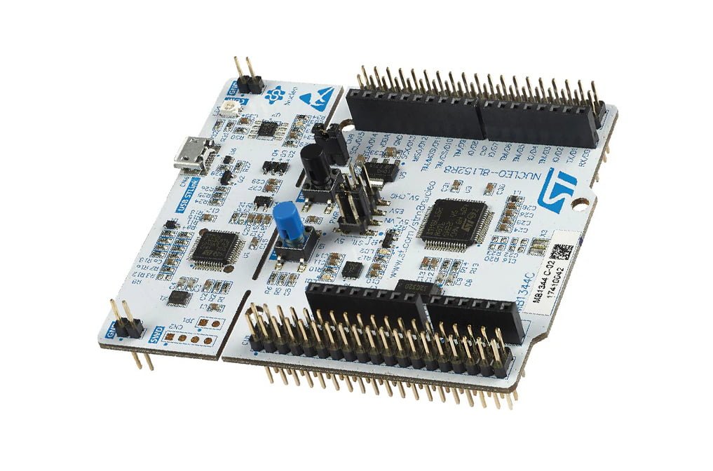
The NUCLEO-8L152R8 and NUCLEO-8S208RB are the first Nucleo-64 boards to integrate STM8 microcontrollers (MCUs), enabling flexible prototype designs through compact MCU configurations. The significant difference between these two models lies in their flash memory capacity. The former integrates an STM8L152R8T6 MCU with 64 kB of flash memory, while the latter utilizes an STM8S208RBT6 with 128 kB of storage. They are also the first STM8 development boards with an Arduino™ Uno V3 connector, allowing developers to use familiar shields, free plugins, and popular programming examples. Furthermore, in collaboration with Cosmic, we provide free compilers with STVD-STM8 IDE or Arduino IDE, enabling developers to develop software for our STM8 MCUs in C++ for the first time without purchasing a toolchain.
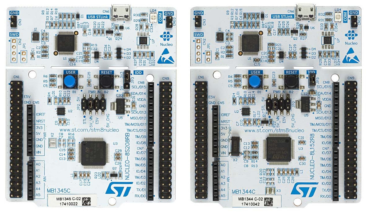
We have found STM32 Nucleo boards to be particularly popular for prototype design and development. They also offer a wide selection of expansion boards that are now compatible with NUCLEO-8L152R8 and NUCLEO-8S208RB since all Nucleo models provide Arduino connectors. This means engineering teams can reuse the same hardware, saving costs and, more importantly, reducing development time as they are already familiar with stacking extensions on the new STM8 Nucleo boards. Therefore, it is now easier to add functionality to our 8-bit systems, enabling more complex and smarter designs in increasingly smaller packages.
STM8 Nucleo Specifications
- Board with MCU types:
NUCLEO-8L152R8 – Based on the STMicroelectronics STM8L152R8T6 8-bit MCU, operating at a frequency of 16 MHz, with 64 kB flash, 2 kB EEPROM, and 4 kB SRAM.
NUCLEO-8S208RB – Based on the STMicroelectronics STM8S208RBT6 8-bit MCU, operating at a frequency of 24 MHz, with 128 kB flash, 2 kB EEPROM, and 6 kB SRAM.
4x LEDs – USB connection indicator (LD4), 5V STLINK indicator (LD3), user LED (LD2), and power indicator (LD1).
2 x buttons – User buttons and a RESET button.
32.768 kHz external crystal oscillator, exclusive to the NUCLEO-8L152R8 development board.
USB – 1-channel microUSB interface as a virtual COM port, on-chip memory interface, and debug interface.
- Expansion connectors:
Arduino UNO V3 interface.
ST morpho expansion interface, including all I/Os for STM8.
Debug – On-board ST-LINK/V2-1 debugger and programmer with SWIM connector and microUSB port.
Power – Powered by USB VBUS or external power (3.3V, 5V, 7 – 12V).
Power management access points.
STM8 Nucleo-64 Development Board Project
This project describes how to control an STM8 Nucleo-64 development board from a terminal window running on a PC. The terminal is connected to the UART of either STM8S208RBT6 (for NUCLEO-8S208RB) or STM8L152R8T6 (for NUCLEO-8L152R8) using an RS232 cable.
After adding the necessary components to the development board and downloading the application software, users can manage GPIO and TIM3 timers of the STM8S or STM8L series and configure the buzzer output using terminal software.
Required Components
The following components are required to run the STM8 Nucleo-64 development board terminal demo application:
- Terminal window running on a PC: Terminal emulation software can be Windows HyperTerminal, TeraTerm Pro, or other terminal software.
- RS232 null modem cable (with crossed transmit and receive lines).
Configuring the NUCLEO-8S208RB Development Board
Before running the application, the NUCLEO-8S208RB development board (based on STM8S208RBT6 device) must be configured to enable the buzzer output. Buzzer output is a multiplexed function of STM8S208RBT6. This function is enabled by setting the remap option bit AFR7 in the OPT2 option byte to “1.”
Note: The NUCLEO-8L152R8 development board (based on STM8L152R8T6 device) does not require users to check or activate the remap function or buzzer.
Application Instructions
Hardware Requirements
This application uses the onboard LED (LD2) and the connected resistor (R1) on the STM8 Nucleo-64 board. External passive components required by the application are listed in the table below:
| Component | Value |
|---|---|
| Buzzer B1 | - |
| Capacitors C1, C2, C3, C4, C5 | 100 nF |
| DB9 Connector | - |
The application also uses a 5V-powered RS232 driver/receiver ST232B (for more details, see the table below). This additional component is essential because the PC’s COM port operates on a standard 12V power supply. This is incompatible with the UART inputs/outputs of STM8S or STM8L series devices, which operate at 5V. The device is in an SO16 package, matching the STM8 Nucleo-64 development board’s package. For more information about the ST232B, refer to the ST232B datasheet.
| Model | Component Description | Package |
|---|---|---|
| ST232B | Ultra-Fast, Ultra-Low-Power 5V RS232 Driver/Receiver for UART 5/12V Level Conversion | SO16 |
Application Schematic
The following diagram illustrates the electrical schematic of the application. If the RS232 cable is not a null modem cable (transmit and receive lines are not crossed), connect U1 pin 14 to DB9 pin 2 and U1 pin 13 to DB9 pin 3.
Application Rules
This application establishes standard communication between the STM8S208RBT6 or STM8L152R8T6 microcontroller and the terminal window running on a PC. Communication is done using the RS232 protocol through the UART of the STM8 device. Both the terminal window and UART must be configured in the same way.
Running the Application
To run this application, follow these steps:
- Launch and configure a terminal window on your PC (refer to section B: Configure the Terminal Window, in this case, using Windows HyperTerminal).
- Compile and run the application firmware using ST Visual Develop (STVD) or another toolchain.
- Connect the PC to the STM8 Nucleo-64 development board using an RS232 cable.
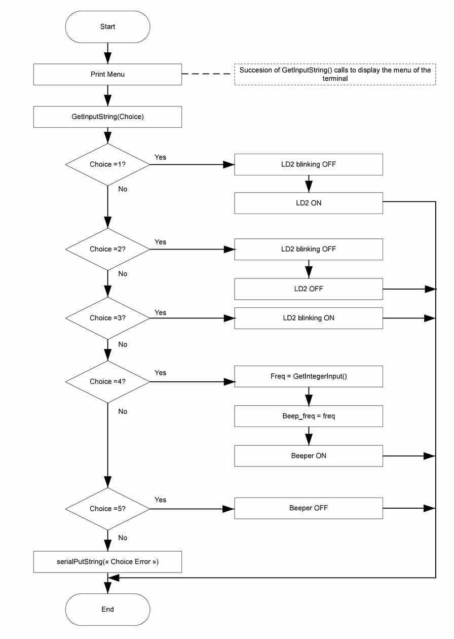
- After the application starts, a menu will be displayed on Windows HyperTerminal. This menu allows users to:
- Turn on or off the LD2 LED.
- Set LD2 to blink mode.
- Enable/disable the buzzer and select the buzzer sound frequency.
All information displayed on this menu is sent by the STM8S or STM8L series microcontroller. When a key is pressed in HyperTerminal, the corresponding ASCII value is sent to the microcontroller, which then decodes it.
Communication Sequence between STM8 Nucleo-64 Development Board and Terminal
- The STM8S or STM8L series microcontroller sends the string “Enter your choice” to the PC terminal emulator software.
- The terminal displays the string “Enter your choice.”
- The user presses the “2” key on the keyboard.
- The terminal emulator software sends the corresponding ASCII code (0x52) back to the microcontroller (see Appendix A: Standard ASCII Character Codes).
- The microcontroller decodes the received data and sends back the code 0x52 to be displayed on the terminal and stores the value “2” in memory.
- The terminal emulator software receives code 0x52 and displays “2.”
- The user presses the “Return” key.
- The terminal emulator software sends back the code 0x0D corresponding to the carriage return (see Appendix A: Standard ASCII Character Codes).
- The STM8S or STM8L series microcontroller decodes the received data, sends back code 0x0D to be displayed on the terminal, and performs the operation associated with option 2.
Windows HyperTerminal
STM8S and STM8L Peripheral
This application example uses the STM8S and STM8L standard firmware libraries to control general functions. The following peripherals are used in this application:
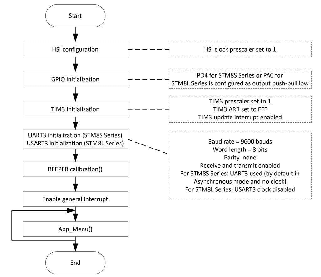
- Timer3 (TIM3): TIM3 timer is configured as a timebase, with interrupts enabled to control the LD2 blinking speed.
- GPIOs: GPIOs are used to connect the MCU to external hardware. Port PC5 for STM8 series or PB5 for STM8L series is configured as a push-pull output to drive LD2.
- BEEPER: To drive the buzzer, the BEEPER peripheral outputs a 1, 2, or 4 kHz signal on the BEEP output pin.
- ART3 for STM8S series or USART3 for STM8L series: Used for communication with the terminal window running on the PC.
ART3 or USART3 needs to be configured as follows:
- Baud rate = 960
- Data length = 8 bits
- 1 stop bit
- No parity
- Enable receive and transmit
(Note: If using the STM8L series, USART3 clock must be disabled.)
Communication is managed by polling for each receive and transmit operation.
(Note: The terminal window and STM8 device UART peripheral must be configured with the same baud rate, data length, stop bits, and parity.)
STM8 Standard Firmware Library Configuration
STM8S Series Standard Firmware Library
The stm8s_conf.h file of the STM8S series standard firmware library allows enabling peripheral functions for use in the application by configuring the library. The following define statements need to be declared:
- #define _GPIO 1 to enable GPIO
- #define _TIM3 1 to enable TIM3
- #define _BEEPER 1 to enable BEEPER
- #define _UART3 1 to enable UART3
STM8L Series Standard Firmware Library
The stm8l_conf.h file of the STM8L series standard firmware library allows enabling peripheral functions for use in the application by configuring the library. The following include statements need to be declared:
- #include “stm8l15x_gpio.h”
- #include “stm8l15x_tim2.h”
- #include “stm8l15x_tim3.h”
- #include “stm8l15x_beep.h”
- #include “stm8l15x_usart.h”
Application Software Flowchart
This section explains the main loop of the application software and the functions controlling data reception/sending to/from the terminal:
- App_Menu: This function is used to display a menu on the terminal and manage user input.
- SerialPutString: This function is used to send strings to the terminal.
- SerialPutChar: This function is used to send individual characters to the terminal.
- GetInputString: This function is used to receive and store strings sent from the terminal.
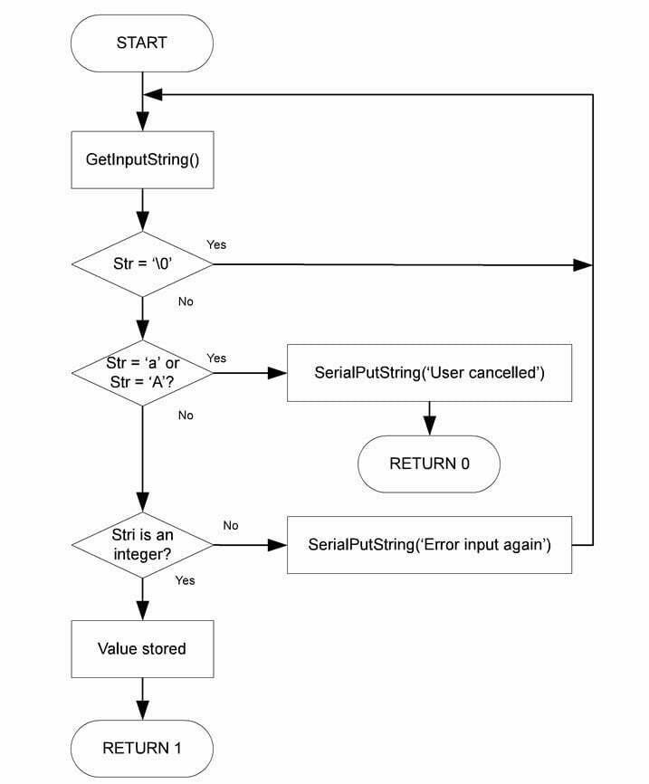
- GetIntegerInput: This function is used to receive integers from the terminal.
- Get_Key: This function returns the corresponding hexadecimal code when a key is pressed.
Main Function of the Application
The main function of the application configures STM8S or STM8L series peripherals and enables standard interrupts for all peripherals used by the application. After initialization, the main program displays the application menu on the terminal window.
App_Menu Function
The App_Menu function is the core of the application. It displays a menu on the terminal, allowing configuration of GPIO, TIM3, and the buzzer. App_Menu calls GetInputString, GetIntegerInput, and SerialPutString to send and receive data via the RS232 interface.
GetInputString Function
The GetInputString function is used to receive and store strings sent from the terminal window. This function relies on the Get_Key function to obtain and decode each character (see Appendix for details). Different actions are taken based on the ASCII value of the character:
If ASCII code = ‘\b’ (backspace): The terminal has sent a backspace. If the string is not empty, it deletes the last character from the string.
If ASCII code is within {0…9} or {A…Z}: The character is stored in the string.
If ASCII code = ‘\r’ (carriage return): The GetInputString function stores a “string end” value ‘\0’ at the end of the string. The maximum number of ASCII codes stored in the buffP[bytes_read] buffer is reached. The software erases the recorded string and waits for another input from the terminal.
Get_Key Function
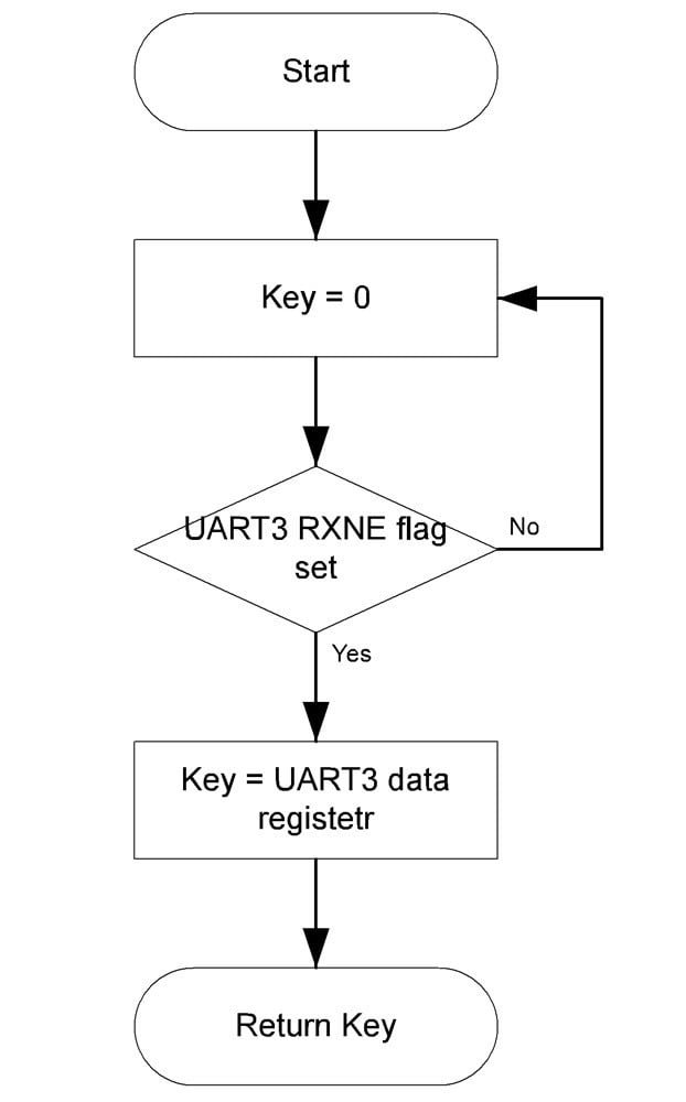
The Get_Key function is used to detect keyboard input on the terminal by polling the UART RXNE flag. It returns the received value.
SerialPutString and SerialPutChar Functions
SerialPutString is used to send strings to the terminal via UART. String characters are sent one by one using the SerialPutChar function, as described in the flowchart.
GetIntegerInput Function
The GetIntegerInput function checks whether the incoming data corresponds to an integer. If it does, the data is stored in memory; otherwise, the user is prompted to enter new data.
