ST’s STM32 Nucleo development boards encompass a range of options, including NUCLEO-F030R8 (supporting STM32F0), NUCLEO-F103RB (supporting STM32F), NUCLEO-F401RE (supporting STM32F4), and NUCLEO-L152RE (supporting STM32L1). These boards offer various combinations of performance, power efficiency, and features. The STM32 Nucleo development boards integrate the ST-Link debugger/programmer and are compatible with various development environments such as IAR EWARM, Keil MDK, mbed, and GCC-based IDEs (Atollic TrueStudio). This makes it easy to prototype new STM32 MCU applications. This article provides an overview of the key specifications and block diagram of the STM32 NUCLEO-F401RE board, along with programming examples for STM32 Nucleo development boards.
NUCLEO-F401RE Board Introduction
The NUCLEO-F401RE development board, also known as NUCLEO-64, features the STM32F401RET6 microcontroller. This controller is based on the high-performance Arm® Cortex®-M4 32-bit RISC core, running at a clock frequency of up to 84MHz. The Cortex-M4 core includes a single-precision Floating-Point Unit (FPU) and supports all Arm single-precision data processing instructions and data types. It also incorporates a complete set of DSP instructions and a Memory Protection Unit (MPU) for enhanced application security. The STM32 NUCLEO-F401RE development board provides an affordable and flexible way for users to experiment with a combination of performance and power features offered by STM32 microcontrollers. It eliminates the need for separate probes, as it integrates the ST-LINK/V2-1 debugger. The STM32 NUCLEO-64 Demo board comes with a comprehensive free software library and examples provided by the STM32Cube MCU package.
Technical Specifications
- MCU: STM32F401RET6, 512K flash, 96K RAM, LQFP64 package
- Built-in ST-LINK/V2-1 (with SWD programming/debug interface)
- Demo board power supply options: USB Vbus or external 5V supply
- 3 LED indicators
- 2 user buttons and one Reset button
- 768kHz crystal oscillator
- Free software library and examples – STM32Cube MCU package
Block Diagram

NUCLEO-F401RE Programming - Serial Communication
This programming exercise aims to understand the usage of USART1 serial communication and involves two tasks:
- Upon board power-up, send the string “System Start!” to the host computer.
- When the host computer sends the hexadecimal number 0xA1 to the development board, immediately respond with the string “a1.”
Required Tools:
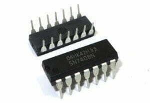
- Development board: NUCLEO-F401RE (Nucleo64), USB to TTL module, 4 jumper wires
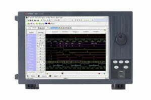
- Development tool: CubeIDE v1.6, serial debugging tool
Hardware Connections
Use UART1: UART1 (TX pin: GPIOA9, RX pin: GPIOA10)

Graphical Configuration
Set debug mode.

Configure the serial port as USART1.
Writing Code in CubeIDE
In the main.c file, define the data transmission string and the callback function for serial port interrupts, as shown below:

Check if the data received on USART1 is 0xA1, respond accordingly, and enable the interrupt-driven receive function to continue waiting for incoming data.
In the main function in the main.c file, send “System Start!” on power-up (line 101) and enable the interrupt-driven receive function (line 104).

Debug and Run the code – Connect the development board to the computer’s USB port. The debugging and running results will be as shown below:


As shown in the screenshot, the development board has successfully sent a message to the computer.