This comprehensive guide is your one – stop resource to explore everything there is to know about the HC-SR04. We’ll start from the very basics, understanding its fundamental working principle, which is the key to unlocking its potential. Then, we’ll move on to cover important aspects such as its key specifications, how to interface it with popular microcontrollers, and even delve into advanced usage scenarios. By the end of this guide, you’ll be well – equipped to leverage the full potential of the HC-SR04 in your own projects.
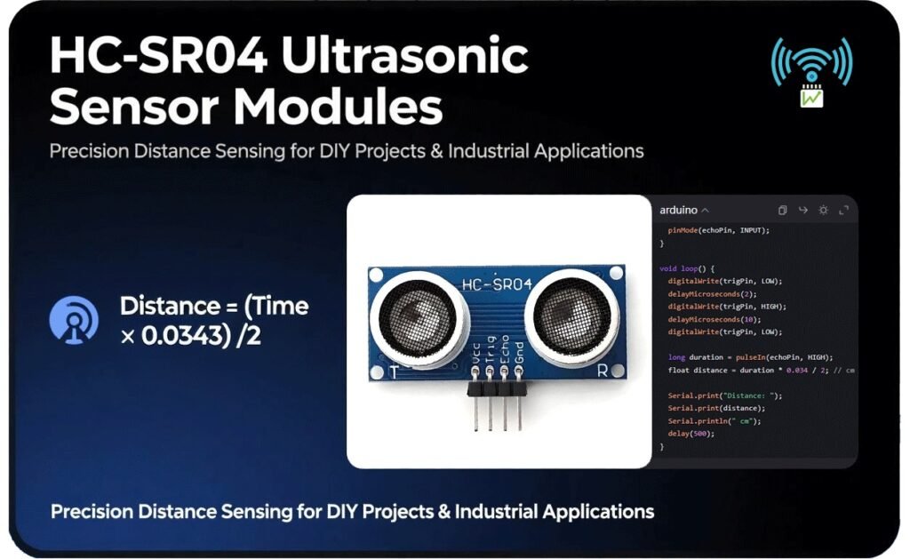
What is HC-SR04 ultrasonic sensor module?
The HC-SR04 ultrasonic sensor module is a remarkable and highly versatile device that has carved a niche for itself in the vast landscape of electronics projects. What makes it truly stand out is its cost-effectiveness, a feature that makes it accessible to a wide range of users, from budget-conscious hobbyists to professionals looking for an affordable solution for their projects.

Technical Specifications
Understanding the technical specifications of the HC – SR04 ultrasonic sensor module is crucial for any project implementation. Here’s the table of tech spec:
Explanation:
- Range: The HC – SR04 has an operational range spanning from 2 cm to 400 cm (0.8 in to 157 in). This relatively wide range makes it suitable for a variety of applications. For example, in a small – scale robotics project where the robot needs to navigate in a room, the 2 – 400 cm range can effectively detect nearby furniture or walls. In a larger – scale industrial application, it can be used to measure the distance between machinery components within this range. However, it’s important to note that the accuracy may vary slightly at the extreme ends of this range.
- Resolution: With a resolution of 0.3 cm, the HC – SR04 can provide fairly precise distance measurements. This level of precision is sufficient for most hobbyist and many industrial applications. In a 3D – printing – related project where the sensor is used to detect the distance to the print bed for auto – leveling, the 0.3 cm resolution can ensure that the printer head is at the correct height above the bed, resulting in high – quality prints.
- Power Supply: It operates on a 5V DC power supply. During operation, it draws an operating current of 15mA, which is relatively low – power consumption. In standby mode, the current draw is even less, less than 2mA. This makes it an energy – efficient choice for battery – powered projects. For instance, in a battery – operated IoT sensor node that uses the HC – SR04 for distance sensing, the low – power consumption ensures that the battery can last for an extended period.
- Operating Angle: The operating angle of the HC – SR04 is less than 15°. This means that the sensor has a relatively narrow field of view. It is most effective at detecting obstacles that are directly in front of it. In a smart – home security system where the sensor is used to detect intruders approaching a door, the narrow operating angle allows for focused detection of objects coming straight towards the sensor, reducing false alarms from objects in the peripheral area.
- Interface: The module features a 4 – pin interface, which includes VCC, GND, Trig, and Echo pins. This simple interface design makes it easy to connect to various microcontrollers and other electronic components.
Pinout Explained
Raspberry Pi: 5V (Common ground with module)
▶ 10μs High Pulse to Start Measurement
▶ Low Level to Reset
Raspberry Pi: Any GPIO (e.g., GPIO17)
▶ High Duration = Round-Trip Time of Ultrasonic Waves
▶ Max High Time: 38ms (Timeout for No Obstacle)
Raspberry Pi: GPIO with **Voltage Divider** (5V→3.3V)
Raspberry Pi/GND
Explanation:
The Echo pin is the key to obtaining the distance information. Once the ultrasonic waves are sent out, the Echo pin goes high. It remains high until the reflected waves are received by the ultrasonic receiver. The duration for which the Echo pin is high is directly proportional to the time it takes for the ultrasonic waves to travel to the obstacle and back. By measuring this time duration, we can calculate the distance to the obstacle using the formula . In a C++-based Arduino project, you can use the pulseIn() function to measure the duration of the high-level pulse on the Echo pin.
Core Components and Working Principle
Key Components
- Ultrasonic Transmitter: This is the component responsible for the initial step in the distance – measuring process. It emits ultrasonic waves at a frequency of 40kHz. These high – frequency waves are inaudible to the human ear but are the key to the sensor’s operation. When triggered, the transmitter sends out these waves into the surrounding environment. Think of it as a powerful speaker that emits sound waves at a frequency far beyond what we can hear. In a robotics application, for example, the ultrasonic transmitter on a robot would send out these 40kHz waves in the direction the robot is moving, preparing to detect any obstacles in its path.
- Ultrasonic Receiver: As the name implies, the ultrasonic receiver’s job is to capture the ultrasonic waves that have been reflected back from any obstacles in the sensor’s range. Once the transmitter sends out the waves, they travel through the air until they hit an object. The waves then bounce back, and it’s the receiver’s task to pick up these reflected waves. It’s like a highly sensitive microphone that can detect the faintest echoes of the ultrasonic waves. In a home automation system where the HC – SR04 is used to detect the presence of a person in a room, the receiver would catch the waves that bounce back from the person’s body.
- Control Circuit: This is the brains behind the operation. The control circuit manages the entire signal – processing sequence. It coordinates the actions of the transmitter and the receiver. When it receives a trigger signal, it instructs the transmitter to emit the ultrasonic waves. Then, it carefully monitors the receiver for the incoming reflected waves. Once the waves are received, the control circuit calculates the time it took for the waves to travel to the obstacle and back. Based on this time and the known speed of sound in air, it computes the distance to the obstacle. In an industrial setting, the control circuit in an HC – SR04 used for automated machinery would precisely manage these operations to ensure accurate distance measurements for the proper functioning of the machinery.
How It Works
Now that we know about the key components, let’s take a step – by – step look at how the HC – SR04 actually measures distance.
Trigger Signal:
The process begins with a trigger signal. When a 10μs high pulse is applied to the Trig (Trigger) pin of the HC – SR04 module, it’s like giving the sensor a “start” command. This short but significant electrical pulse initiates the entire distance – measuring sequence. For instance, in an Arduino – based project, you would use a simple line of code to send this 10μs high pulse to the Trig pin of the HC – SR04, telling it to begin the measurement process.
Wave Propagation:
Once triggered, the ultrasonic transmitter swings into action. The module sends out a burst of 8 ultrasonic pulses at a frequency of 40kHz. These pulses are like a series of invisible “sonic bullets” that shoot out into the environment. After sending these pulses, the module then enters a waiting state, patiently waiting for the waves to hit an obstacle and bounce back. In a real – world scenario, if you were using the HC – SR04 to measure the distance to a wall in a room, the 8 pulses would travel towards the wall, spreading out in a cone – like shape with a relatively narrow angle of about 15 degrees.
Echo Detection:
The Echo pin is the key to detecting the reflected waves. As soon as the ultrasonic waves are sent out, the Echo pin goes high. This is the sensor’s way of indicating that it has started the measurement process. Then, it waits for the reflected waves to return. When the ultrasonic receiver captures the reflected waves, the Echo pin goes low. The duration for which the Echo pin remains high is equal to the round – trip travel time of the ultrasonic waves. In a Raspberry Pi project, you would use a function to measure the time the Echo pin is high, which is a crucial step in calculating the distance.
Distance Calculation:
Distance Calculation: The final step is to calculate the distance to the obstacle. The formula for calculating the distance in centimeters is . The factor 0.0343 comes from the speed of sound in air, which is approximately 343 m/s. Since the waves travel to the obstacle and back (a round-trip), we divide the total distance traveled by 2 to get the one-way distance to the obstacle. For example, if the time measured for the Echo pin to be high is 2000μs, then the distance would be calculated as cm. This calculation is the same whether you're using the HC-SR04 in a simple hobbyist project or a complex industrial application.
Interfacing with Popular Microcontrollers
Arduino Setup Guide
Wiring Diagram
- VCC: Connect the VCC pin of the HC – SR04 to the 5V pin of the Arduino. This provides the necessary power to the sensor module. A stable 5V power supply from the Arduino ensures that the sensor functions optimally.
- GND: The GND (Ground) pin of the HC – SR04 should be connected to the GND pin of the Arduino. This establishes a common ground reference for both the sensor and the Arduino, which is crucial for proper electrical communication.
- Trig: Connect the Trig (Trigger) pin of the HC – SR04 to digital pin 2 of the Arduino. This is the pin where the Arduino will send the 10μs high – level pulse to trigger the distance – measurement process in the HC – SR04.
- Echo: The Echo pin of the HC – SR04 is connected to digital pin 3 of the Arduino. The Arduino will read the high – duration pulse on this pin to calculate the distance to the obstacle.
					       HC - SR04         Arduino
         VCC ------------ 5V
         GND ------------ GND
         Trig ------------ Digital Pin 2
         Echo ------------ Digital Pin 3
Code Example
					const int trigPin = 2;
const int echoPin = 3;

void setup() {
  Serial.begin(9600);
  pinMode(trigPin, OUTPUT);
  pinMode(echoPin, INPUT);
}

void loop() {
  digitalWrite(trigPin, LOW);
  delayMicroseconds(2);
  digitalWrite(trigPin, HIGH);
  delayMicroseconds(10);
  digitalWrite(trigPin, LOW);

  long duration = pulseIn(echoPin, HIGH);
  float distance = duration * 0.0343 / 2;

  Serial.print("Distance: ");
  Serial.print(distance);
  Serial.println(" cm");

  delay(500);
}
In the setup function, we first initialize the serial communication at a baud rate of 9600, which allows us to view the distance readings in the Arduino Serial Monitor. Then, we set the trigPin as an output pin and the echoPin as an input pin.
In the loop function, we start by setting the trigPin to LOW for 2 microseconds to ensure a clean start. Then, we set it HIGH for 10 microseconds to trigger the ultrasonic transmitter in the HC-SR04. After that, we set the trigPin back to LOW.
The pulseIn() function is then used to measure the duration of the high-level pulse on the echoPin. This duration represents the time it took for the ultrasonic waves to travel to the obstacle and back. We then calculate the distance using the formula distance = duration * 0.0343 / 2, where 0.0343 is the speed of sound in cm/μs and we divide by 2 because the waves travel to the obstacle and back.
Finally, we print the calculated distance to the Serial Monitor and add a 500-millisecond delay before the next measurement.
Tips
- Accurate High - Duration Measurement:
When using the pulseIn() function, it's important to note that it measures the duration of a pulse. In the case of the HC-SR04, this is the time the Echo pin is high. To ensure accurate measurements, make sure there are no other electrical interferences that could affect the pulse duration. Also, be aware that if the obstacle is too far away, the pulse may time out. You can set a timeout value in the pulseIn() function to handle such cases gracefully. For example, long duration = pulseIn(echoPin, HIGH, 20000); where 20000 is the timeout value in microseconds.
- Avoiding Noise Sources:
Ultrasonic waves can be affected by loud noise sources. When placing the HC – SR04 in your project, avoid areas with high – intensity sound, such as near speakers or in a very noisy industrial environment. Noise can interfere with the ultrasonic waves emitted by the sensor, leading to inaccurate distance measurements. If you must use the sensor in a noisy area, consider using sound – absorbing materials or enclosures to shield the sensor from the noise.
Raspberry Pi Integration
Voltage Caution
To solve this issue, you can use a voltage divider circuit. A simple voltage divider using a 1kΩ and a 2kΩ resistor can be used to convert the 5V output from the Echo pin of the HC-SR04 to a 3.3V-compatible signal for the Raspberry Pi. The formula for calculating the output voltage of a voltage divider is , where is the input voltage (5V in this case), is the first resistor (1kΩ), and is the second resistor (2kΩ). Plugging in the values, we get , which is within the safe range for the Raspberry Pi GPIO pin.
Wiring
- VCC: Connect the VCC pin of the HC – SR04 to the 5V pin on the Raspberry Pi. This powers up the HC – SR04 sensor module.
- GND: The GND pin of the HC – SR04 should be connected to the GND pin on the Raspberry Pi to establish a common ground.
- Trig: Connect the Trig pin of the HC – SR04 to GPIO 17 on the Raspberry Pi. The Raspberry Pi will use this pin to send the 10μs high – level trigger pulse to the HC – SR04.
- Echo: The Echo pin of the HC – SR04, after passing through the voltage divider circuit (1kΩ and 2kΩ resistors), is connected to GPIO 27 on the Raspberry Pi. The Raspberry Pi will read the high – duration pulse on this pin to calculate the distance.
					       HC - SR04         Raspberry Pi
         VCC ------------ 5V
         GND ------------ GND
         Trig ------------ GPIO 17
         Echo (through voltage divider) ------------ GPIO 27
Python Code
					import RPi.GPIO as GPIO
import time

# Set the GPIO mode
GPIO.setmode(GPIO.BCM)

# Define the pins
TRIG = 17
ECHO = 27

# Set up the pins
GPIO.setup(TRIG, GPIO.OUT)
GPIO.setup(ECHO, GPIO.IN)

def measure_distance():
    # Send a 10μs high - level pulse to trigger the sensor
    GPIO.output(TRIG, True)
    time.sleep(0.00001)
    GPIO.output(TRIG, False)

    # Wait for the echo to start
    while GPIO.input(ECHO)==0:
        pulse_start = time.time()

    # Wait for the echo to end
    while GPIO.input(ECHO)==1:
        pulse_end = time.time()

    pulse_duration = pulse_end - pulse_start
    distance = pulse_duration * 17150  # Speed of sound in cm/s divided by 2
    distance = round(distance, 2)

    return distance

try:
    while True:
        dist = measure_distance()
        print(f"Distance: {dist} cm")
        time.sleep(1)

except KeyboardInterrupt:
    print("Measurement stopped by User")
    GPIO.cleanup()
In this code, we first import the necessary libraries, RPi.GPIO for controlling the GPIO pins on the Raspberry Pi and time for adding delays. We then set the GPIO mode to BCM (Broadcom SOC channel numbering). We define the TRIG and ECHO pins and set up the TRIG pin as an output and the ECHO pin as an input.
The measure_distance function is where the magic happens. It sends a 10μs high - level pulse to the TRIG pin to trigger the HC - SR04. Then, it waits for the ECHO pin to go high (indicating the start of the echo) and records the start time. It then waits for the ECHO pin to go low (indicating the end of the echo) and records the end time. The time difference between the start and end times is used to calculate the distance. The distance is calculated by multiplying the pulse duration by the speed of sound in cm/s (34300 cm/s) and dividing by 2 (since the sound travels to the obstacle and back).
In the try block, we continuously measure the distance and print it to the console every second. If the user presses Ctrl + C (KeyboardInterrupt), the program cleans up the GPIO pins and exits gracefully.
ESP32 Configuration
Pin Assignment
Arduino IDE Code
					const int trigPin = 14;
const int echoPin = 15;

void setup() {
  Serial.begin(115200);
  pinMode(trigPin, OUTPUT);
  pinMode(echoPin, INPUT);
}

void loop() {
  digitalWrite(trigPin, LOW);
  delayMicroseconds(2);
  digitalWrite(trigPin, HIGH);
  delayMicroseconds(10);
  digitalWrite(trigPin, LOW);

  long duration = pulseIn(echoPin, HIGH);
  float distance = duration * 0.0343 / 2;

  Serial.print("Distance: ");
  Serial.print(distance);
  Serial.println(" cm");

  delay(500);
}
In the setup function, we initialize the serial communication at a baud rate of 115200. We then set the trigPin as an output pin and the echoPin as an input pin.
In the loop function, the process of triggering the HC - SR04 and measuring the distance is the same as in the Arduino code. We send a 10μs high - level pulse to the trigPin to trigger the sensor, measure the duration of the high - level pulse on the echoPin using pulseIn , and calculate the distance.
Creative Project Ideas Using HC-SR04
Obstacle-Avoiding Robot
The sensors are configured to detect obstacles from different directions. For example, a set of sensors is placed at the front of the robot to detect any obstacles directly in its forward – moving path. Additionally, sensors are placed on the sides of the robot to detect obstacles that may be approaching from the sides. When an obstacle is detected, the robot’s control system, which is often based on a microcontroller like Arduino, calculates the distance to the obstacle using the data from the HC – SR04 sensors.
Based on this distance information, the control system then determines the appropriate action to take to avoid the obstacle. This usually involves steering the motors in a way that changes the robot’s direction. For instance, if an obstacle is detected on the left – hand side of the robot, the control system may instruct the left – hand motor to slow down or reverse while the right – hand motor continues to run at a normal speed. This causes the robot to turn to the right, away from the obstacle.
To build this project, you will need several key components. An Arduino serves as the brain of the operation. It processes the data received from the HC – SR04 sensors and sends commands to the motors. Motors are required to drive the wheels of the robot, enabling it to move. A motor driver, such as the L298N, is essential for controlling the motors. The L298N can handle the relatively high – current requirements of the motors and allows the Arduino to control the speed and direction of the motors effectively. And of course, multiple HC – SR04 sensors are needed for front and side detection. By combining these components and writing the appropriate code to control them, you can create a fully functional obstacle – avoiding robot.
Smart Trash Can
The HC – SR04 sensor is mounted on the trash can in such a way that it can detect the distance to any objects in front of it. When someone approaches the trash can, the sensor measures the distance between the trash can and the person. If the measured distance falls below a pre – set threshold (for example, 20 cm), it indicates that a person is close enough to the trash can to need to use it. At this point, the sensor sends a signal to a servo motor.
The servo motor is connected to the lid of the trash can and is responsible for opening and closing it. When it receives the signal from the HC – SR04 sensor, the servo motor rotates to open the lid. This hands – free operation is not only convenient for the user but also helps to keep the trash can clean and hygienic as there is no need to touch the lid directly.
When writing the code for this project, setting the distance threshold is a crucial step. You need to carefully calibrate this value based on the specific requirements of your smart trash can. If the threshold is set too high, the lid may open unnecessarily when someone is still some distance away from the trash can. On the other hand, if the threshold is set too low, the lid may not open in time when the user approaches. A well – calibrated distance threshold ensures that the smart trash can functions optimally.
Water Level Monitor
The HC – SR04 sensor is installed above the water tank. It emits ultrasonic waves downwards towards the water surface. These waves travel through the air and bounce back when they hit the water surface. The sensor then measures the time it takes for the waves to travel to the water surface and back. Using the known speed of sound in air, the distance from the sensor to the water surface can be calculated.
In many cases, the water level monitor is integrated with an IoT (Internet of Things) system. For example, it can be connected to a Blynk app. The calculated water level data is sent to the app, allowing users to monitor the water level remotely. This is especially useful for industrial applications where real – time monitoring of water levels is crucial for the proper functioning of processes.
One important aspect to consider when setting up a water level monitor is calibration. Since the sensor is installed at a certain height above the base of the tank, this height needs to be accounted for in the distance calculations. For example, if the sensor is installed 50 cm above the base of the tank, and the calculated distance from the sensor to the water surface is 30 cm, then the actual water level in the tank is 20 cm. By accurately calibrating the sensor height and performing the necessary calculations, you can ensure that the water level monitor provides accurate and reliable readings.
Troubleshooting Common Issues
Inconsistent Readings
Cause: Multi - path reflections or unstable power
Unstable power is another culprit. If the power supply to the HC – SR04 is not stable, it can cause the sensor to malfunction. Voltage fluctuations can affect the proper functioning of the ultrasonic transmitter and receiver, leading to erratic distance measurements. For instance, if you’re using a battery that is running low or a power adapter with poor voltage regulation, the sensor may not receive a consistent 5V power supply, which can impact its performance.
Fix: Add a protective casing for the sensor and use a regulated 5V power source
Using a regulated 5V power source is crucial for stable operation. A power supply with built – in voltage regulation, such as a high – quality wall adapter or a voltage – regulated power module, ensures that the HC – SR04 receives a consistent 5V. This helps to eliminate any issues caused by voltage fluctuations and improves the overall accuracy and consistency of the sensor’s readings.
No Output Signal
If you’re using the HC – SR04 with a Raspberry Pi, don’t forget to check the voltage divider circuit. As mentioned earlier, the Raspberry Pi’s GPIO pins can only handle 3.3V, and a voltage divider is often used to convert the 5V output from the Echo pin of the HC – SR04 to a 3.3V – compatible signal. If the voltage divider components (usually resistors) are damaged or incorrectly connected, it can result in no output signal being received by the Raspberry Pi.
The code logic for trigger/echo timing is also a critical area to check. Make sure that the code is sending the correct trigger signal (a 10μs high – level pulse) to the Trig pin and that it’s correctly measuring the duration of the high – level pulse on the Echo pin. Incorrect code can prevent the sensor from being triggered or can cause the microcontroller to misinterpret the echo signal, leading to no output or incorrect distance calculations. For example, if the delay times in the code are set incorrectly, it can disrupt the proper sequence of triggering the sensor and reading the echo.
Out - of - Range Errors
Handling 0 or ∞ (infinity) values gracefully in code is also important. A distance value of 0 may indicate that the sensor is too close to an object, closer than its minimum detectable range. In such cases, you may want to set a minimum distance threshold in your code and adjust the distance value accordingly. Similarly, if the code calculates a distance value that is extremely large (approaching infinity), it’s likely an indication of an error, such as a problem with the echo detection or incorrect calculations. Your code should be able to handle these cases gracefully, for example, by logging an error message or attempting to re – measure the distance.
HC-SR04 vs. Other Distance Sensors
vs. Infrared Sensors
HC-SR04
Range: 2cm–400cm (Abstract 1, 6)
Accuracy: ±3mm (ideal conditions, Abstract 1)
Voltage: 5V (fixed, Abstract 1)
Pros: No light interference, longer range (Abstract 5)
Cons: Reduced near-range accuracy, ultrasonic noise sensitivity (Abstract 1)
Infrared
Range: Typically <100cm (Abstract 1, 5)
Accuracy: ±5mm–1cm (affected by color/material, Abstract 5)
Voltage: 3.3V–5V (flexible, Abstract 5)
Pros: Small size, low cost (Abstract 1)
Cons: Ambient light/color interference (Abstract 5)
The table 1 highlights the trade-off between HC-SR04’s robust long-range detection (2cm–400cm) and infrared sensors’ compact size/low cost, noting HC-SR04’s immunity to light interference vs. infrared’s vulnerability to ambient light and material color.
vs. Laser Sensors
HC-SR04
Range: 2cm–400cm (Abstract 1, 4)
Accuracy: ±3mm (Abstract 4)
Update Rate: 60ms (Abstract 4)
Cost: ~$2–3 (Abstract 1)
Weakness: 15° cone angle, environmental noise (Abstract 1)
Laser/ToF (VL53L0X)
Range: 5cm–200cm (Abstract 1, 3)
Accuracy: ±1mm–3mm (Abstract 3)
Update Rate: 20ms (faster, Abstract 4)
Cost: ~$10–15 (Abstract 1)
Strength: 5° narrow beam, interference-resistant (Abstract 3)
The table 2 compares HC-SR04’s cost-effectiveness ($2–3) and wide range (400cm) with Laser/ToF sensors’ superior precision (±1mm) and speed (20ms update rate), ideal for applications requiring high accuracy in controlled environments.
vs. US - 100 Module
HC-SR04
Range: 2cm–400cm (Abstract 2, 6)
Accuracy: ±3mm (nominal, Abstract 2)
Voltage: 5V only (Abstract 6)
Feature: GPIO-only, no temperature compensation (Abstract 3)
Issue: Random values beyond 400cm (Abstract 6)
US-100
Range: 2cm–450cm (Abstract 2, 3)
Accuracy: ±2mm (better in tests, Abstract 3)
Voltage: 3.3V–5V (Abstract 3)
Feature: Temperature compensation (UART mode), error codes (Abstract 6)
Downside: Higher cost ($5–8), UART setup required (Abstract 3)
The table 3 showcases US-100’s enhanced range (450cm), better accuracy (±2mm), and 3.3V/5V compatibility against HC-SR04’s simplicity (GPIO-only), highlighting US-100’s temperature compensation feature for industrial use at a higher cost ($5–8).
Advanced Techniques and Optimizations
Multi-Sensor Calibration
However, when using multiple sensors, cross – talk interference can become a significant issue. Cross – talk occurs when the ultrasonic waves emitted by one sensor interfere with the operation of another sensor. This can lead to inaccurate readings as the sensors may misinterpret the interfering waves as echoes from actual obstacles.
To mitigate cross – talk interference, several techniques can be employed. One approach is to time – multiplex the sensors. This involves activating the sensors one at a time, with sufficient time intervals between each activation. For example, if you have four HC – SR04 sensors on a robot, you can activate sensor 1, wait for it to complete its measurement cycle, then activate sensor 2, and so on. By doing this, you ensure that the ultrasonic waves from one sensor do not overlap with those of another sensor, reducing the chances of cross – talk.
Another technique is to use shielding materials. Placing a physical barrier, such as a thin sheet of metal or a sound – absorbing material, between the sensors can help block the ultrasonic waves from one sensor from reaching another. This can be especially useful in situations where the sensors are placed in close proximity to each other.
Calibration is also crucial when using multiple sensors. Each sensor may have slightly different characteristics, such as sensitivity or beam angle. By calibrating the sensors, you can account for these differences and ensure that the data from all sensors is consistent. This may involve measuring the distance to a known object with each sensor and adjusting the readings based on the differences.
Noise Filtering
One commonly used method is the moving average filter. The moving average filter works by calculating the average of a series of consecutive distance readings. For example, instead of using a single distance reading, you can take the last 5 readings and calculate their average. This smooths out the jittery readings, as the small fluctuations tend to cancel each other out when averaged. In Python, the implementation of a simple moving – average filter for the HC – SR04 distance readings could look like this:
					distance_readings = []
num_readings = 5

def moving_average_filter(new_distance):
    distance_readings.append(new_distance)
    if len(distance_readings) > num_readings:
        distance_readings.pop(0)
    return sum(distance_readings) / len(distance_readings)
Another effective filtering method is the median filter. The median filter replaces each distance reading with the median value of a set of consecutive readings. The median is less sensitive to extreme values or outliers compared to the mean. For example, if you have a set of 5 distance readings [20, 22, 18, 50, 21], the median value is 21. By using the median filter, the outlier value of 50 would not significantly affect the filtered result. In Arduino, the implementation of a median filter could be as follows:
					const int numReadings = 5;
int readings[numReadings];
int readIndex = 0;
int total = 0;
int averageDistance = 0;

void addReading(int newReading) {
  total = total - readings[readIndex];
  readings[readIndex] = newReading;
  total = total + readings[readIndex];
  readIndex = readIndex + 1;
  if (readIndex >= numReadings) {
    readIndex = 0;
  }
}

int getMedian() {
  int sortedReadings[numReadings];
  for (int i = 0; i < numReadings; i++) {
    sortedReadings[i] = readings[i];
  }
  for (int i = 0; i < numReadings - 1; i++) {
    for (int j = i + 1; j < numReadings; j++) {
      if (sortedReadings[i] > sortedReadings[j]) {
        int temp = sortedReadings[i];
        sortedReadings[i] = sortedReadings[j];
        sortedReadings[j] = temp;
      }
    }
  }
  return sortedReadings[numReadings / 2];
}
Custom Work Modes
However, there are also UART (Universal Asynchronous Receiver/Transmitter) and I2C (Inter – Integrated Circuit) modes available on certain HC – SR04 versions. In UART mode, the module can communicate with a microcontroller using serial communication. This can be useful in applications where a more standardized serial communication protocol is preferred, such as in some industrial control systems or when integrating with devices that have built – in UART interfaces.
The I2C mode, on the other hand, enables communication over an I2C bus. This is beneficial in multi – device setups where multiple sensors or components need to communicate with a single microcontroller. The I2C bus allows for a more efficient use of the microcontroller’s pins, as multiple devices can share the same two – wire bus (SDA – Serial Data Line and SCL – Serial Clock Line).
To configure the module for these custom modes, you need to refer to the module’s documentation to determine the appropriate resistor values. For example, to enable UART mode, you may need to connect a specific resistor between two pins on the module. Once the resistors are correctly configured, the module can be programmed to communicate in the desired mode. This may involve writing different code in your microcontroller to handle the UART or I2C communication protocols. For instance, in a Raspberry Pi project using the I2C – configured HC – SR04, you would use the smbus library in Python to communicate with the sensor over the I2C bus.