Microchip’s tinyAVR® family of microcontrollers with Core Independent Peripherals (CIP), high-speed internal oscillators and event systems has been widely admired. Microchip’s newly launched megaAVR® MCU – ATmega4809 series has larger storage capacity and more pins, and is an expansion of the tinyAVR series. This new ATmega4809 series is an ideal auxiliary MCU for complex systems using microprocessors, and can become an excellent stand-alone processor in command-control system designs.
ATmega4809 Features
As the first megaAVR device to integrate core-independent peripherals (CIP), the ATmega4809 performs tasks in hardware rather than software. It also extends the capabilities of real-time control systems by combining intelligent hardware peripherals with the low-power features of the AVR® core.
- 8-bit AVR® CPU with hardware multiplier
- Flash memory up to 48 KB
- Up to 16 channels of high-speed 10-bit ADC
- Configurable custom logic peripherals
- Integrated high-speed analog-to-digital converter (ADC)
These features make the new megaAVR series of microcontrollers ideally suited for use as companion MCUs in microprocessor-based systems, or as a perfect stand-alone processor in command/control system designs.
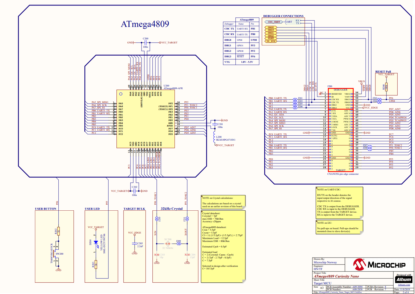
ATmega4809 Curiosity Nano Schematic
ATmega4809 Startup Code
Tools required
- Hardware: ATmega4809 Curiosity Nano development board
- Software: MPLAB X IDE v5.5, XC8 compiler
Compile option settings
By default, the default startup code (built-in to MicroChip) is used in MPLAB. If you want to use DIY startup code in your project, you need to set the following compilation options:
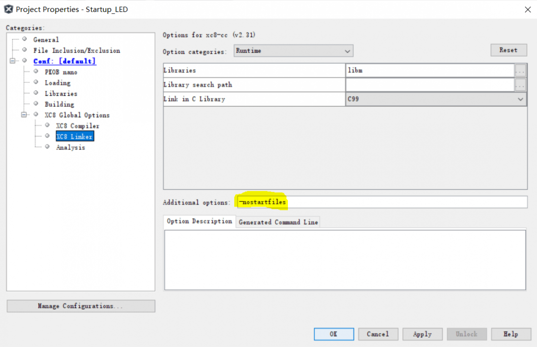
Select the project and open the project properties panel. Add the “-nostartfiles” option in Additional Options and save the changes.
MCU interrupt function processing
When there is no jump statement, the code is run one by one from the beginning. When an interrupt occurs, the program will automatically jump to the corresponding interrupt entry address, and the interrupt entry address is a continuous address. Generally, we call this continuous interrupt entry address an interrupt vector table. Because the memory space corresponding to the interrupt entry address is only 16 bits (2 bytes), this space cannot save our interrupt service function code at all. So we will place a jump statement at the interrupt entry address to jump to the entry address of our interrupt service function to execute our interrupt service function.
Startup code - assembly version
					/* This file uses not the AVRASM2.exe assembler but the gnu assembler as - the GNU assembler */
/* Replace the rjmp command with jmp */

     #include <xc.h>

     .extern main; refers to the main function in the Main.c file

/* Interrupt vector table. Place jump instructions. When an interrupt occurs, jump to the corresponding interrupt service function to execute the interrupt function */
     .section .vectors
     jmp __ctors_end;
     jmp CRCSCAN_NMI
     jmp BOD_VLM
     jmp RTC_CNT_MEGA4809
     jmp RTC_PIT
     jmp CCL_CCL
     jmpPORTA_PORT
     jmp TCA0_OVF_vect


/* Code storage area that runs before the main function is run */
     .section .init2
     clr r1; Clear r1 register. Some compilers require this
     clr r16; Clear SREG status register
     out SREG, r16
     ; Init the STACK Pointer. Initialization stack. Used for calling sub-functions
     ldi r16,(RAMEND & 0xff); initialize
     out CPU_SPL,r16; stack pointer.
     ldi r16,(RAMEND >> 8) ; to RAMEND
     out CPU_SPH,r16

     .section .init9
     rcall main ; jump to main function
     jmp 0x00; Function executed after the main function ends. Jump directly to 0x00 to reset the MCU

  // code space
.section .text

//interrupt service function
.weak CRCSCAN_NMI; Use the .weak directive to define the function. When this function is defined externally, the externally defined function is used
.globalCRCSCAN_NMI
CRCSCAN_NMI:
     reti

.weak BOD_VLM
.global BOD_VLM
BOD_VLM:
     reti

.weak RTC_CNT_MEGA4809
.global RTC_CNT_MEGA4809
RTC_CNT_MEGA4809:
     reti

.weak RTC_PIT
.globalRTC_PIT
     RTC_PIT:
     reti

.weak CCL_CCL
.global CCL_CCL
     CCL_CCL:
     reti

.weakPORTA_PORT
.globalPORTA_PORT
     PORTA_PORT:
     reti

.end
Test code
Compile the test code of this startup file in the main function to detect whether the startup we wrote can enter the TCA0 overflow interrupt.
					#include "mcc_generated_files/mcc.h"

volatile uint8_t flag = 0;

int main(void)
{
     /* Initializes MCU, drivers and middleware */
     SYSTEM_Initialize();

     /* Replace with your application code */
// protected_write_io(&(CLKCTRL.MCLKCTRLB),IO_KEY,0x01);
     PORTF.DIR = 0x20;
     TCA0.SINGLE.PERH = 0x4C;
     TCA0.SINGLE.PERL = 0x4B;
     TCA0.SINGLE.CTRLA = 0x0D;
     TCA0.SINGLE.INTCTRL = 0x01;
     ENABLE_INTERRUPTS();

     while(1)
     {
         if(flag==1)
         {
             flag = 0;
             PORTF.OUTTGL = 0x20;
         }
     }
}

ISR(TCA0_OVF_vect)
{
     flag = 1;
     TCA0.SINGLE.INTFLAGS = 0x01;//??????
}
ATmega4809 Development Case - GPIO Output
Tools required
- Hardware: ATmega4809 Curiosity Nano development board
- Software: Microchip Studio 7
Create a new project
Create a new project in Microchip Studio 7 and add a new folder to it.
Select the project, then right-click and select Add >> New Folder

Add files to folder, select C file and enter the C file name VPORT.c
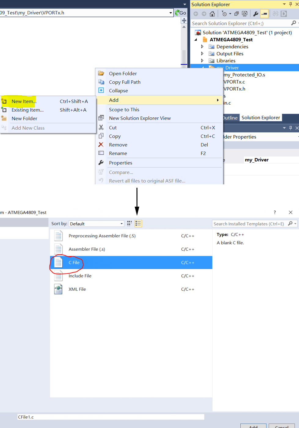
Follow the same method to create a new VPORT.h file.
Set the header file path
Open the project settings window, click the project settings to set the header file path:
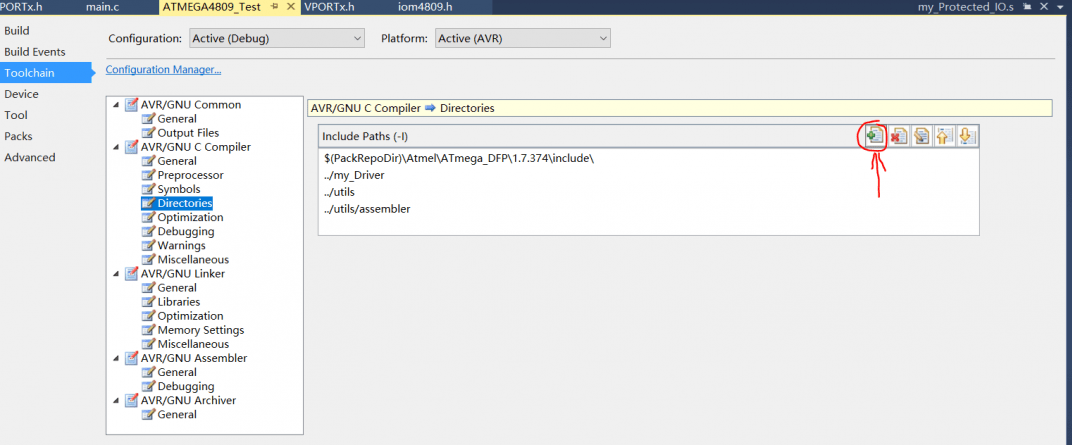
Write the code
We use structures to operate peripherals. Because the memory address occupied by the structure is continuous like the array, and when we check the chip manual, we will also find that the VPORTF peripheral register group address is also connected. So we can assign the VPORF register base address to the structure pointer.
					typedef struct VPin_x_Jack{
         uint8_t PIT_0: 1;
         uint8_t PIN_1: 1;
         uint8_t PIN_2: 1;
         uint8_t PIN_3: 1;
         uint8_t PIN_4: 1;
         uint8_t PIN_5: 1;
         uint8_t PIN_6: 1;
         uint8_t PIN_7: 1;
}VPINx_Jack_TypeDef;

typedef struct VPort_x_Jack{
         VPINx_Jack_TypeDef DIR;
         VPINx_Jack_TypeDef OUT;
         VPINx_Jack_TypeDef IN;
         VPINx_Jack_TypeDef INTFLAGS;
}VPORTx_Jack_TypeDef;


#define VPORTA_Jack (*(VPORTx_Jack_TypeDef *)0x0000)
#define VPORTB_Jack (*(VPORTx_Jack_TypeDef *)0x0004)
#define VPORTC_Jack (*(VPORTx_Jack_TypeDef *)0x0008)
#define VPORTD_Jack (*(VPORTx_Jack_TypeDef *)0x000C)
#define VPORTE_Jack (*(VPORTx_Jack_TypeDef *)0x0010)
#define VPORTF_Jack (*(VPORTx_Jack_TypeDef *)0x0014)
Pin header file in main.c file
					#include <avr/io.h>
#include "VPORTx.h"

extern protected_write_io(void *addr, uint8_t KEY,uint8_t value);


static inline void System_Clock_Setting(void *addr,uint8_t value)
{
         protected_write_io(addr,0xD8,value);
}


void LED_Init(void)
{
         VPORTF_Jack.DIR.PIN_5 = 1; // PF5 output
         VPORTF_Jack.OUT.PIN_5 = 1; // LED off
}


int main(void)
{

         //Configure the system clock to 10MHZ
         System_Clock_Setting((void *)&(CLKCTRL.MCLKCTRLB),CLKCTRL_PDIV_2X_gc | 1 << CLKCTRL_PEN_bp);
         //Initialize LED port
         LED_Init();

     while (1)
     {
     }
}
LED light control code:
Check the circuit diagram to confirm that the IO port connected to the LED pin is PF5. Since the positive terminal of the LED is connected to the power supply, when the negative terminal of the LED is low, the LED is lit. Otherwise, the LED goes out.
					VPORTF_Jack.OUT.PIN_5 = 1; // LED off
VPORTF_Jack.OUT.PIN_5 = 0; // LED is on
Debugging code
As shown in the figure below, configure the project as Simulator and use the simulation debugger for code debugging.
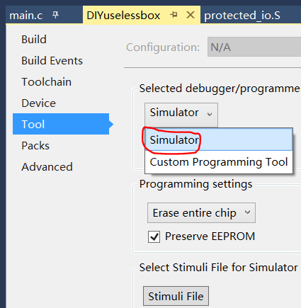
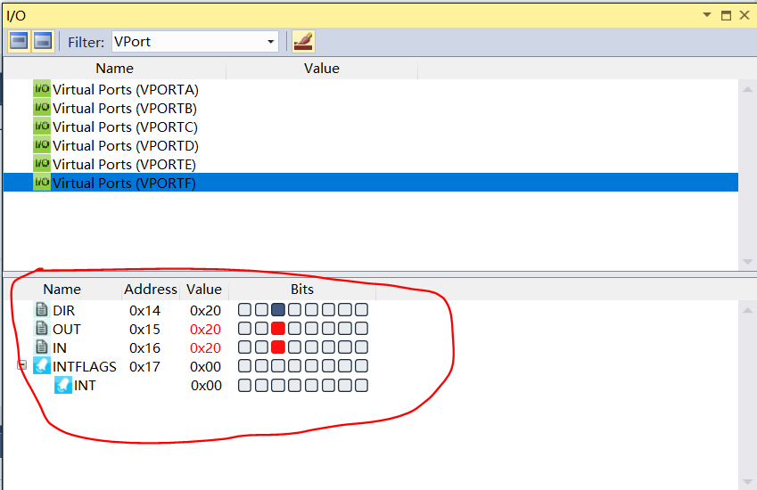
Open I/O View to view the pin register status.
