About SAMD21 Microcontroller
The SAM D21/DA1 is a family of low-power microcontrollers using a 32-bit Arm® Cortex®-M0+ processor and ranging from 32 to 64 pins with up to 256 KB of Flash and 32 KB of SRAM. The SAM D21/DA1 operates at a maximum frequency of 48 MHz, reaching 2.46 CoreMark/MHz. They are designed for easy and intuitive migration with the same peripheral modules, hex-compatible code, identical linear address map and pin-compatible migration path between all devices in the product family. All devices include smart and flexible peripherals, event system for inter-peripheral signaling, and support for capacitive touch buttons, sliders, and wheels for user interfaces.
Features of SAMD21
The SAM D21 microcontrollers are supported by a comprehensive set of program and system development tools, including C compilers, macro assemblers, program debuggers/simulators, programmers and evaluation kits.
- Core Processor: ARM® Cortex®-M0+
- Core Specifications: 32-bit single core
- Speed: 48MHz
- Connectivity: I²C, LINbus, SPI, UART/USART, USB
- Peripherals: Brown-out detection/reset, DMA, I²S, POR, PWM, WDT
- Number of I/Os: 26
- Program memory capacity: 128KB (128K x 8)
- Program Memory Type: Flash
- EEPROM Capacity: Depends on Specific Model
- RAM size: 16K x 8
- Voltage – Supply (Vcc/Vdd): 1.62V ~ 3.63V
- Data Converter: A/D 10x12b; D/A 1x10b
- Oscillator Type: Internal
- Working temperature: -40°C ~ 125°C (TA)
- Mounting Type: Surface Mount Type
- Package/Case: 32-VFQFN Exposed Pad
- Vendor Device Package: 32-QFN (5×5)
SAMD21 Xplained Pro Development Board Programming
This part requires you to have your own SAM D21 Xplained Pro evaluation kit so you can follow along. A USB cable is also required, which is not included in the development kit. If you haven’t used it yet, download and install Atmel Studio first.
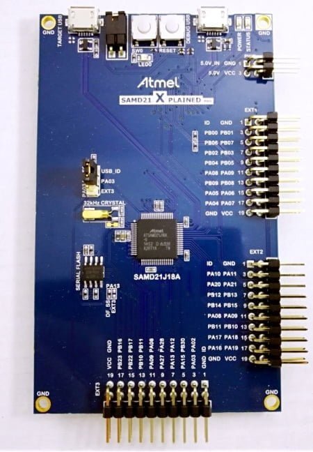
At first, please open Atmel Studio and connect the Xplained Pro development board to the computer with a USB cable. The development board has two USB ports: one port is marked “DEBUGE USB”, which is used for Atmel Studio debugging and programming; the other port is marked “TARGET USB”, which can be used to develop USB applications. In this example, we just need to program the board, so connect the USB cable to the DEBUG USB. Atmel Studio will recognize the board and may inform you that the board’s firmware is out of date. If this happens, update the firmware before following the Atmel Studio instructions.
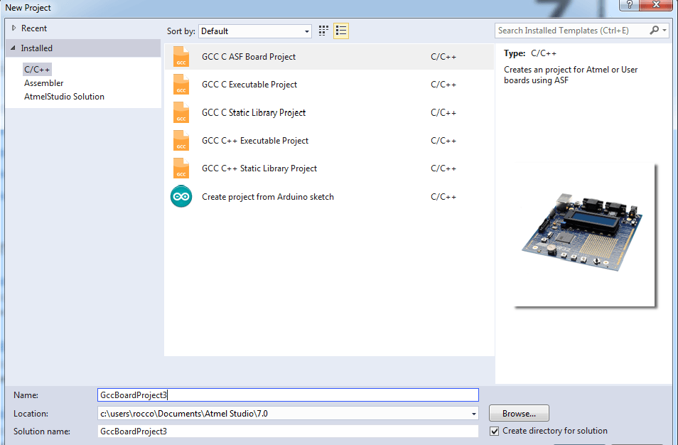
Next, go to the menu bar and click on File->New->Project. From the pop-up dialog box, select “GCC C ASF Board Project”, give the project a name you want, and click OK.
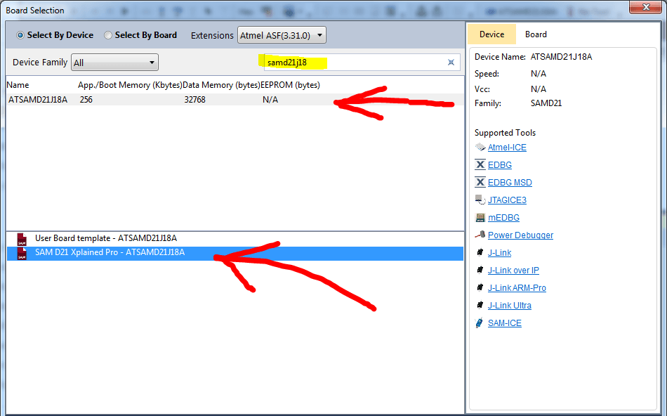
Next, select the appropriate development board. We need to find the SAM D21 Xplained Pro development board in the list. This can be done by clicking on the “Select By Device” checkbox and typing “SAMD21J18” in the search bar. The list will filter the results, and then you can find and select “SAM D21 Xplained Pro – ATSAMD21J18A”. Then click OK and Atmel Studio will create the project.
On the right you will see a panel labeled “Solution Explorer”. Go to “src > main.c” and double-click main.c to open it. We will see that Atmel Studio has created a skeleton code for us, which can be edited. We don’t need to modify it for this example. We only want to flash the default routine code into the memory of SAM D21. If we look closely at the comments and code, we can see that the function of the sample code created by Atmel Studio is: when we press Button0 (labeled SW0 on the development board), LED0 will be turned on.
In order to flash our simple firmware into the development board, all we need to do is hit the green play button. The button is “start without debugging”. Then the development board will immediately start executing the code to program the SAMD21.
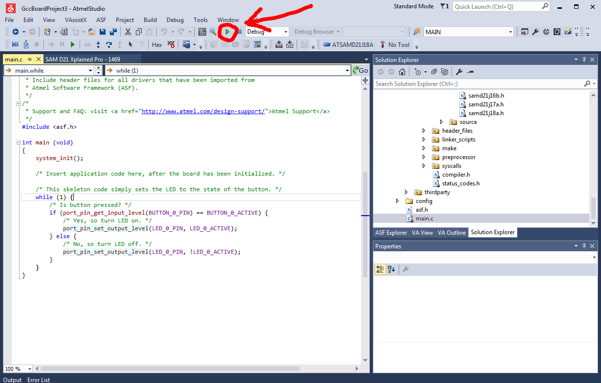
Once you click “start without debugging”, an output console dialog box will pop up, prompting “Build Succeeded”, which means that the code is valid. Otherwise, if there is a compilation error, you will see the following prompt:
If the project is compiled successfully, you can see “Ready” in the lower left corner of the screen. The code can now be tested. Press the SW0 button and you should see LED0 light up. Release the button and LED0 will turn off. Now, you can write your own code according to your needs.


