If you have been working on a DIY 3D printer, CNC machine, or RepRap-style electronics setup, you may have seen the term “RAMP PCB” or “RAMPS board.” It can be confusing at first because people often use slightly different names for the same type of controller board. In most search results, RAMP PCB refers to a RAMPS-style printed circuit board used to control motors, heaters, fans, sensors, and other parts of a 3D printer.
This guide explains what a RAMP PCB is, how it works, where it is used, what connectors and circuits it usually includes, and what to check before buying, repairing, or reverse engineering one.
What Does RAMP PCB Mean?
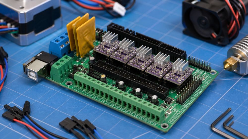
A RAMP PCB usually refers to a RAMPS-style controller board, most commonly the RepRap Arduino Mega Pololu Shield. RAMPS boards became popular in open-source 3D printers because they combine an Arduino Mega with plug-in stepper driver modules and connectors for printer hardware.
The term RAMPS is often written in uppercase, but users may search for “ramp pcb,” “ramps pcb,” or “RAMP board.” In practical use, they usually mean the same general category: a PCB that connects the printer control system to motors, endstops, heaters, thermistors, fans, and power input.
The PCB itself is not the full controller by itself. In the classic RAMPS 1.4 setup, the RAMPS board plugs into an Arduino Mega 2560. The Arduino runs the firmware, while the RAMPS shield provides screw terminals, driver sockets, connectors, MOSFET outputs, fuses, and routing for the printer’s electrical loads.
What Is a RAMPS Board Used For?
A RAMPS board is used to control the main electrical functions of a 3D printer or similar motion-control machine. It connects low-level firmware commands to real hardware such as stepper motors, heaters, fans, and limit switches.
In a typical 3D printer, the board controls the X, Y, and Z stepper motors, the extruder motor, the heated bed, the hotend heater, cooling fans, thermistors, and endstop switches. Some versions also support LCD panels, SD card modules, servo outputs, or expansion connectors.
For beginners, the most important point is that the RAMPS PCB acts as a bridge. It does not create motion or heat on its own. It receives control signals from the Arduino or main controller and routes power and signals to the correct printer parts.
Main Parts of a RAMP PCB
A RAMP PCB contains both signal-level circuits and higher-current power circuits. Understanding the main sections makes the board easier to inspect, troubleshoot, or reverse engineer.
The stepper driver sockets are one of the most recognizable areas. These sockets accept plug-in modules such as A4988 or DRV8825 drivers. Each module controls one stepper motor channel, such as X, Y, Z, or extruder.
The motor connectors route the driver outputs to the stepper motors. These are usually four-pin headers. If a motor vibrates but does not rotate, the issue may be a wiring order problem, a weak driver module, or incorrect firmware settings.
The MOSFET output circuits control higher-current loads such as the heated bed, hotend heater, and fans. These circuits switch power on and off based on firmware commands. The heated bed output often carries the most current, so burnt terminals or overheated traces are common failure points on low-quality boards.
The thermistor inputs read temperature sensors. These inputs are usually small signal circuits, and they are sensitive to broken wires, loose connectors, or wrong sensor settings in firmware.
The power input section supplies the board. Many RAMPS boards use separate power paths for motors and heated loads. Always check the board version and wiring diagram before connecting power.
How a RAMP PCB Works in a 3D Printer
A RAMP PCB works by routing control signals and power between the firmware controller and the printer hardware. The Arduino or main controller sends signals such as step, direction, heater on/off, fan control, and sensor reading commands.
When the firmware tells the X-axis to move, the controller sends step and direction signals to the X-axis driver socket. The stepper driver module then sends current through the motor coils. The RAMPS PCB provides the physical connections between the controller pins, driver module, and motor connector.
When the firmware heats the hotend, it activates a MOSFET output. The MOSFET switches power to the heater cartridge. At the same time, the thermistor input reports temperature back to the firmware so the system can regulate the heater.
This is why the PCB layout matters. Motor currents, heater currents, signal traces, connectors, and power input paths all share the same board. Poor layout, weak terminals, thin copper, or poor soldering can cause unstable operation or heat damage.
Good PCB layout guidelines are especially useful here because RAMPS boards mix power routing, motor signals, sensor inputs, and connector-heavy areas.
Common RAMP PCB Versions
RAMPS 1.4 is the most widely recognized version, but it is not the only one. You may also see RAMPS 1.5, RAMPS 1.6, or modified boards based on the same idea.
RAMPS 1.4 is common in older RepRap and DIY printer builds. It uses plug-in driver modules, screw terminals, resettable fuses, and a familiar Arduino Mega shield layout.
RAMPS 1.5 and 1.6 versions often change the power handling, fuse layout, connector style, or copper design. Some versions are designed to handle heat better, while others are simply low-cost clones with small layout changes.
When buying or repairing a board, do not rely only on the printed version number. Check the connector markings, power input rating, MOSFET area, fuse type, driver orientation, and documentation from the seller or manufacturer.
What to Check Before Buying a RAMP PCB
Before buying a RAMP PCB, check whether it matches your controller, firmware, power supply, motors, and printer hardware. A board that looks compatible may still have connector or current-limit differences.
First, confirm the controller type. Classic RAMPS boards are designed for Arduino Mega 2560. If your printer uses a different mainboard architecture, a RAMPS shield may not fit.
Second, check the board version and driver support. Make sure it supports the stepper drivers you plan to use, such as A4988, DRV8825, or compatible modules. Pay close attention to driver orientation because installing a driver backward can damage the board.
Third, inspect the power terminals and MOSFET area. Heated beds draw high current, so poor terminals or weak solder joints can overheat. If your printer uses a powerful heated bed, consider whether the board needs an external MOSFET module.
Fourth, check documentation. A good board should have a clear pinout, power wiring guide, driver jumper settings, and firmware notes.
Common Problems with RAMP PCB Boards
Common RAMP PCB problems include burnt power terminals, failed MOSFETs, loose driver modules, incorrect jumpers, and damaged traces. Many failures come from high current, poor wiring, or wrong driver installation.
Burnt terminals often happen near the heated bed output or main power input. The cause may be too much current, loose screws, low-quality connectors, or repeated heating cycles.
Stepper motor problems may come from driver modules, jumper settings, motor wiring, or firmware current limits. If one axis does not move, swap the driver module with another axis to narrow down the fault.
Temperature reading problems often come from broken thermistor wires, poor connectors, wrong firmware sensor type, or damaged input circuits. A printer that reads an impossible temperature may disable heating for safety.
Fan and heater outputs can fail when MOSFETs are damaged. If firmware commands the heater or fan on but no voltage appears at the output, the MOSFET circuit may need inspection.
How to Inspect or Reverse Engineer a RAMP PCB
To inspect or reverse engineer a RAMP PCB, start with the connector labels, power paths, driver sockets, and MOSFET output circuits. These areas reveal most of the board’s function.
Begin by photographing both sides of the PCB under good light. Capture the silkscreen labels, component markings, driver sockets, screw terminals, fuses, and any burnt or darkened areas.
Next, trace the power input. Follow the thick copper paths from the power terminals to fuses, MOSFETs, motor supply pins, and heater outputs. High-current paths are often wider than signal traces.
If you are not sure how trace width affects current flow, review PCB trace basics before judging whether a power path is strong enough.
Then map the driver sockets. Identify step, direction, enable, motor output, VMOT, GND, and logic pins. Compare them with common A4988 or DRV8825 pinouts.
Finally, inspect small-signal inputs such as endstops and thermistors. These circuits usually connect back to controller pins through headers, pull-up resistors, or filtering components.
If the board is damaged, avoid powering it until you have checked for shorts between power and ground. A quick continuity check can prevent more damage.
For damaged, cloned, or undocumented boards, a PCB reverse engineering service can help identify circuits and recover board data.
RAMP PCB vs Modern 3D Printer Mainboards
A RAMP PCB is modular and easy to understand, while many modern 3D printer mainboards are more integrated. This difference affects cost, repair, noise, performance, and upgrade options.
Classic RAMPS setups use a separate Arduino Mega and plug-in stepper drivers. This makes them easy to modify and repair. If a driver fails, you can often replace only the driver module.
Modern printer boards often include the microcontroller, stepper drivers, MOSFETs, USB interface, display connectors, and expansion ports on one PCB. They may offer quieter drivers, better thermal design, higher voltage support, and cleaner wiring.
RAMPS boards are still useful for learning, repair practice, open-source builds, and simple machines. For new printer designs, a modern integrated board may be a better choice if you need quieter operation, compact wiring, or more reliable current handling.
Conclusion
A RAMP PCB is usually a RAMPS-style controller shield used in 3D printers and other motion-control projects. It connects firmware control signals to motors, heaters, fans, sensors, and power circuits. If you are working with one, start by identifying the board version, connector labels, power input, driver sockets, and MOSFET outputs. For a custom controller, a PCB design service can help turn the circuit into a safer, manufacturable board. For a small first step, inspect your board visually and compare it with a trusted RAMPS wiring diagram before connecting power.