Why RMS Voltage Matters in Real Circuit Measurements
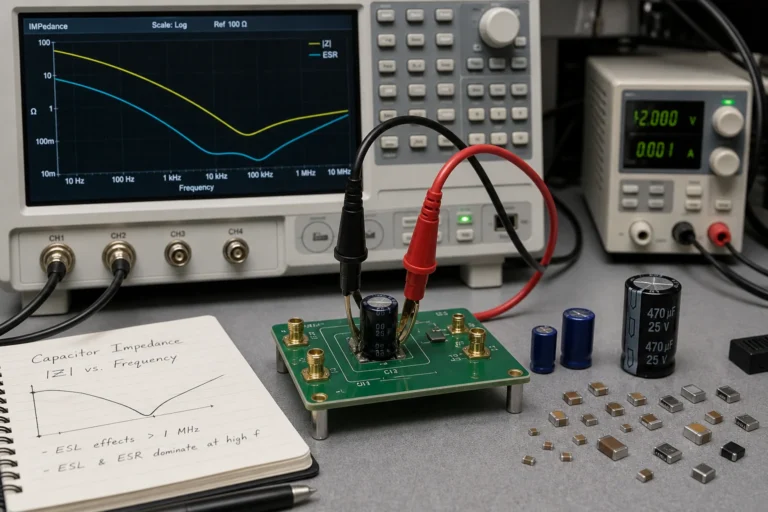
RMS isn’t just a formula from a textbook. Understanding what RMS means in practical terms changes how you measure AC signals, specify components, and avoid thermal miscalculations.
Schematic & Gerber restoration
MCU/CPLD code restore access & backup
1:1 exact hardware replication
BLE & Classic BT wireless solutions
Precision PID & thermal management
High-efficiency motor drive control
Industrial RS485/RTU communication
Custom STM32/ESP32 firmware & HW
Calculate the PCB trace width based on temperature rise, current, and copper thickness (IPC-2152).
Explore the core principles of electronics, from digital circuits and electrical testing to key components like microcontrollers and semiconductors. This category covers important topics such as PCB design, soldering techniques, and the basics of computer architectures like RISC and CISC. Learn about signal processing, electromagnetic compatibility (EMC), and practical guides for working with components like capacitors and amplifiers.

RMS isn’t just a formula from a textbook. Understanding what RMS means in practical terms changes how you measure AC signals, specify components, and avoid thermal miscalculations.

Electronic design automation does more than draw schematics. It defines how a PCB transitions from concept to fabrication data, and the tools you choose affect everything from signal integrity to manufacturing yield.

Learn how to read a G3MB-202P solid-state relay schematic, separate input and load sides, and avoid unsafe assumptions when switching AC loads.

This guide explains how guitar pedal PCBs are laid out, powered, switched, debugged, and prepared for repeatable assembly.

Learn how barrel jack polarity is shown in schematics, how to identify center-positive wiring, and what to verify before powering a circuit board.

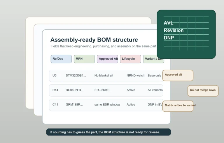
An eBOM and an mBOM should describe the same product, but they do not serve the same job. A practical PCB assembly example makes it easier to see where the handoff fails and what must be reviewed before release.

SMT stands for Surface Mount Technology, but its real meaning runs deeper: it shapes PCB design rules, component choices, assembly workflow, and the cost structure of modern electronics manufacturing.

This article explains how to read a relay schematic as a working switching system rather than a disconnected set of symbols.

A practical guide to PCBA functional testing, including test coverage, fixture design, measurement limits, common assembly faults, and what to verify before shipment.

A practical guide to solder paste inspection in SMT assembly, including SPI metrics, defect patterns, process-control value, and how to use print data to improve yield.