What is PCB Footprint?
PCB footprint, is the arrangement of pads used to mount a specific component to a printed circuit board. The footprint defines the outline of the component and the location of the mounting pads. It’s an important step in pcb reverse engineering. It is displayed graphically so that it can be called when drawing a PCB diagram.
Types of PCB Footprints
There are four types of PCB footprints installation methods: mounted devices, plug-in devices, mixed devices (which have both mounted and plug-in installation), and special devices (sinking devices).
In addition, PCB footprints can be divided into the following categories according to their functions and device shapes:
| Type | Definition |
|---|---|
| SMD | Surface Mount Devices |
| RA | Resistor Arrays |
| MELF | Metal electrode leadless face |
| SOJ | Small Outline J-Lead Package |
| SSOIC | Shrink Small Outline Integrated Circuits |
| SOP | Small Outline Package |
| SSOP | Shrink Small Outline Package |
| TSOP | Thin Small Outline Package |
| TSSOP | Thin Shrink Small Outline Package |
| CFP | Ceramic Flat Packs |
| PQFP | Plastic Quad Flat Pack |
| SQFP | Shrink Quad Flat Pack |
| CQFP | Ceramic Quad Flat Pack |
| PLCC | Plastic leaded chip carriers |
| LCC | Leadless chip carriers |
| QFN | Quad Flat Non-leaded package |
| DIP | Dual-In-Line components |
| PBGA | Plastic Ball Grid Array |
| RF | Radio Frequency Microwave devices |
| DIODE | A thermionic tube having two electrodes |
| LED | Light Emitting Diode |
| TO | Transistors Outlines |
| PGA | Plastic Grid Array |
| RELAY | One kind of electrically operated switches |
| SIP | System-in-package |
The Structure of a PCB Footprint
Generally speaking, a complete footprint includes many different elements, and different components require different elements.

1. Components of Footprint
The components of the footprint include:
sink plate opening size, dimensioning, chamfer size, pad, solder mask, aperture, flower pad, anti-pad, Pin_number, Pin spacing, Pin span, silk screen, assembly line, prohibited wiring area, prohibited hole area, tag character, assembly character, 1-pin mark, installation mark, floor space, device height, etc.
2. Elements of Footprint
A PCB footprint has the following elements:
- PCB pad: a carrier for soldering component pins.
- Pin serial number: the serial number used to match the electrical connection relationship with the component.
- Component silk screen: an identification box used to describe the size of the component cavity.
- Solder mask: place green oil to cover, which can effectively protect the pad welding area.
- 1-pin identification/polarity identification: mainly used to identify the direction of the component.
How to Create PCB Footprints?
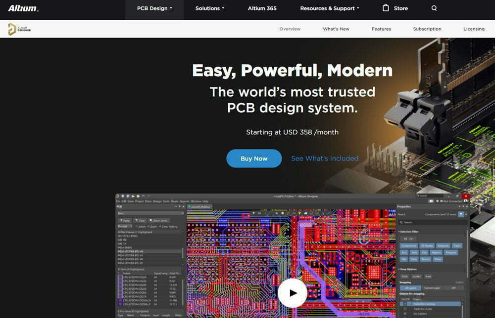
The steps of PCB footprints creation by Altium software are divided into two types: patch type footprint and plug-in type footprint. The specific operation steps are as follows:
patch type footprint
First of all, the production process of the patch type footprint can be as follows:
(1) To make a patch pad, execute the menu command “Place (P) → Pad (P)”, or use the shortcut key “PP”, and press the “TAB” key to modify the properties of the pad in the placement state, as follows as shown in the figure.
(2) “Designator” is the pin number, “Layer” is the pad layer attribute, selecting “Top Layer” or “Bottom Layer” is the patch pad, and selecting “Muti-Layer” is the pin pad.

(3) Modify the pad size, select the placed pad, and press F11 to call up the property box. If the property box already exists, ignore this step.
As shown in the figure below, you can modify the required coordinate position, rotation angle, pad type, pad size, center offset and other defaults in the pad property box. You can only modify it when there are special requirements. After setting, our pads are placed.

(4) Once you finish placing the pad according to the required position, draw the silk screen next. The footprint of the chip needs to be marked with a “1” foot, and execute the menu command “Place → Line”.
After drawing the approximate shape, select the drawn layer, line width and position in the Properties panel, and the silkscreen line width is more than 4mil (usually 0.15mm or 0.2mm), as shown in the figure below.

plug-in type footprint
Secondly, the plug-in type footprint production process can be as follows:
(1) The steps of the production process are the same. You need to select “Muti-Layer” to be the pin pad, and you can set the size of the hole and the plate, as shown in the figure below.

How to create a new PCB Library?
(1) First, execute the menu command “File-New-Library-PCB Library”, create a new PCB library, and the PCB library file named “PcbLib1.PcbLib” by default and a component named “PCBCOMPONENT_1” will appear.
(2) Second, execute the “Save” command to rename the PCB library file to “Demo.PcbLib” for storage.
(3) Third, double-click “PCBCOMPONENT_1” to change the name of this component; you can also right-click in the Footprints column and execute the “New Blank Footprints” command, or execute the menu command “Tools – New Blank Component” to create The new PCB footprint is added to the list of PCB footprints as shown in the image below.

PCB Design and Manufacturing Notes for Effective PCB Footprint Strategies
These additions address practical search intent while preserving the original page structure and existing ranking content.
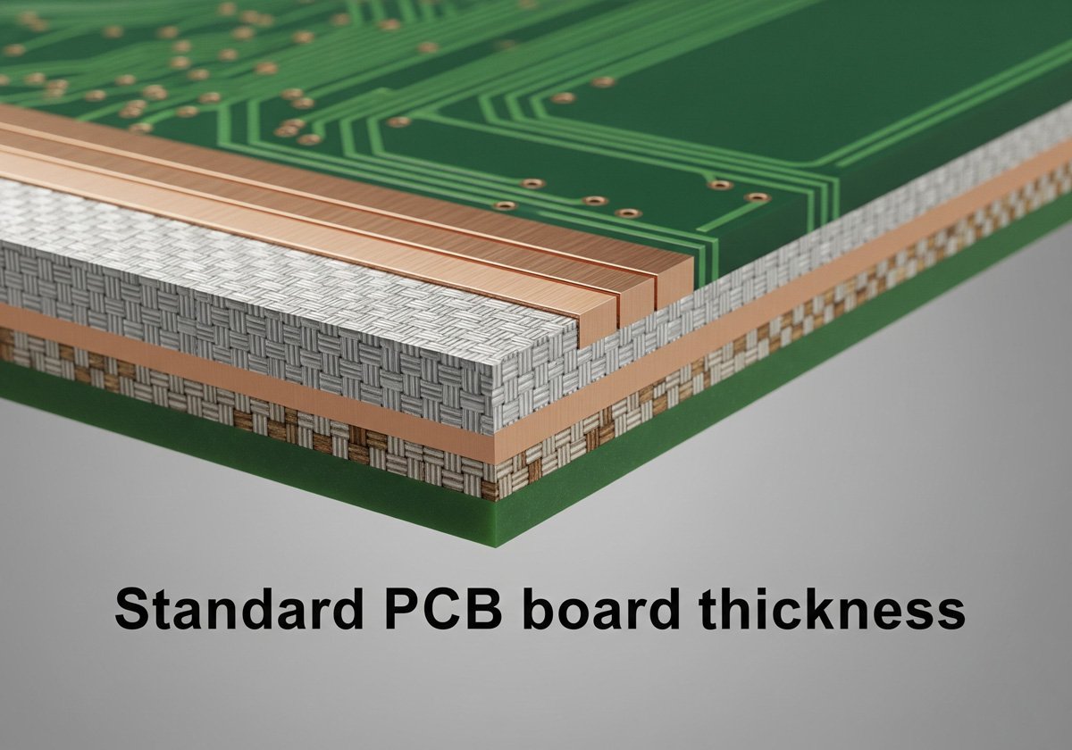
- Define stack-up, laminate, copper weight, minimum trace/space, annular ring, solder mask, and IPC class before releasing fabrication files.
- Run DRC/DFM checks against the chosen manufacturer’s capability table, especially for impedance control, via aspect ratio, solder mask slivers, and drill tolerances.
- Include fiducials, tooling holes, panelization notes, test coupons, and controlled-impedance requirements when the board moves beyond prototype quantity.