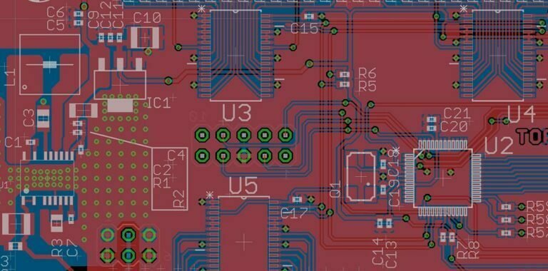
If you’re working on a large design project, it can be difficult to keep track of all the different layers and their associated components. When you’re working on a very specific task, such as adding electrical components to your schematic, it can be even more challenging to find the correct layer at the right time. To help keep your design organized and reduce the risk of going off track, you may want to consider implementing a process of altium rotate board in your design workflow.
This will not only make things easier for you in the long run, but it should also cut down on the amount of time spent searching for pertinent layers. If you would like to learn how to rotate your board in Altium so that all of your files are organized for efficiency and ease of use moving forward, read on for some helpful tips.
What is Altium Rotate Board?
When you rotate the board in your design environment, you’re rotating the layers that are assigned to the board — such as the top and bottom copper layers, the solder mask, and more. This allows you to have a more centralized workflow that makes it easy to access all of your design elements using a simple pattern.
For example, you may have an element of your design residing on Layer 10, Layer 20, and Layer 35. If you rotate your board, all of these layers will shift to Layer 1. This way, you can easily access each layer and all of its associated elements from a central location. This is especially helpful for large and complex design projects where you’ll likely be referencing all of the different layers at some point. With board rotation, finding the right components becomes much less of an ordeal.
How to Rotate Your Board in Altium?
To rotate your board in Altium, select the Layer menu at the top of your screen and select the option for Rotate Board. From here, you can select which layers you’d like to be rotated and in which order. Make sure you select All Copper when choosing layers to rotate, or you may run into issues when placing your design back into the circuit board. After you’ve finished rotating your board, make sure you click the Apply button to save your changes.
You’ll also want to make sure you’re saving your design with each new rotation. If you don’t, your old file will be the only one that is accessible. You’ll want to ensure you’re saving your new design under a new file name and with a new description. This will help you keep track of which file is your most recent and which layer order is being used. Please read the all steps below:
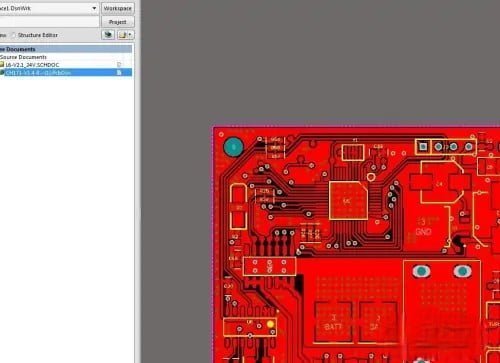
Step1: open pcb file in altium
First, we open the PCB project file that needs to be rotated in the Altium software, and set the display layer to the Top layer, as shown in the following figure.
Step2: select all elements at the top level
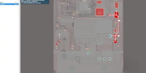
Next, we hold down the left mouse button and move the mouse at the same time to select all elements of the Top layer, as shown in the following figure.
Step3: select the "Rotate Selection" option
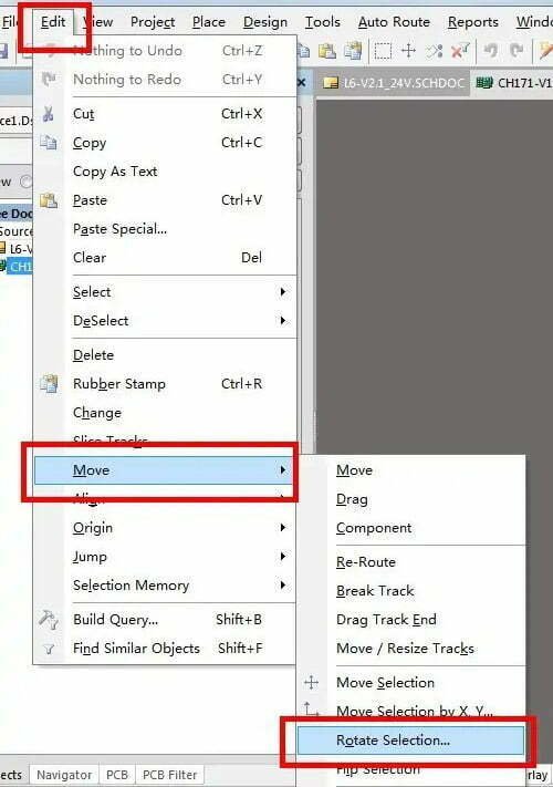
Then, find the “Edit” option at the top left of the interface, click this option and a drop-down box will appear, select the “Move” option in the drop-down box, and select the “Rotate Selection” option in the sub-drop-down box next to it.
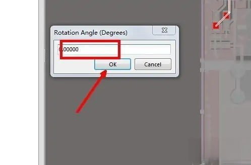
Step4: enter the rotation angle
At this time, the software will pop up a window, we enter the rotation angle in the text box in the window, such as input 30, and then click the “OK” button.
Step5: start to ratate
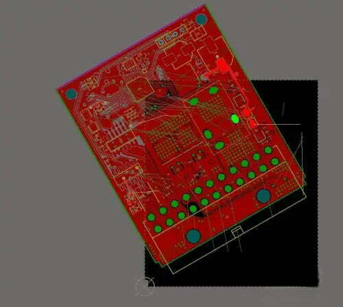
Click on a certain point on the interface, and the PCB will rotate around this point by the set angle, as shown in the figure below.
Step6: rotate bottom layer
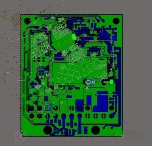
Finally, select the Bottom layer and rotate the bottom PCB according to the above method, and the PCB can be successfully rotated at any angle.
Which Layers Should You Rotate?
The first step in rotating the layers in your design is determining which ones you should rotate. For most board designs, you’ll want to rotate the top and bottom copper layers, the solder mask, the solder paste, and the silkscreen. It’s also a good idea to rotate the layers associated with your components if you’re working with a large design. For example, if you’re working on an electrical schematic, you may want to rotate the layers associated with your resistors, capacitors, ICs, and other components. This will make it easier to find the parts you need and help prevent you from accidentally grabbing the wrong one.
Rotating PCB Layers
As we mentioned above, you’ll want to make sure you rotate the layers for your top and bottom copper layers. You may also want to rotate the solder mask layer if you’re adding or removing a silkscreen design that’s engraved into the solder mask. When you rotate your solder mask layer, the solder mask will shift to the top copper layer so that nothing is engraved on the copper. This will give you room to add your silkscreen design without interfering with your soldering process.
It’s also important to note that rotating your solder mask will make the design unroutable. This means you’ll be unable to send your design to the PCB fabrication company for manufacturing due to design issues. It’s best to keep this in mind when rotating your solder mask layer.
Conclusion
While rotating the board in your design environment sounds easy enough, it can take some time to get used to. Once you’ve gotten the hang of it, it will become second nature and make it easier to keep track of all of your design elements. To help make the process easier, make sure you keep a list of the layers you’re rotating in your design and the order in which they are located. This will make it easier to find the layers you need once you’ve rotated them, and it will also help ensure you don’t forget to rotate any layers when you’re adding new elements to your design.

