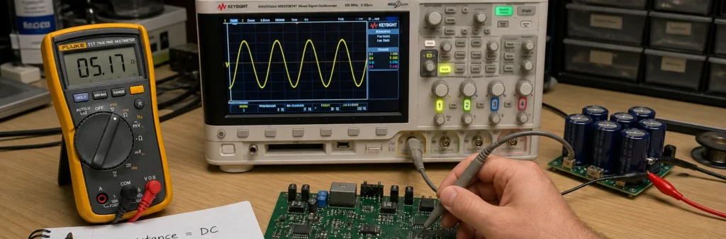
Resistance is easy to recognize when a trace runs hot, a shunt drops too much voltage, or a resistor value drifts out of tolerance. Impedance is where engineers start missing the real behavior, because the circuit can look acceptable at DC and still fail once switching edges, cable length, capacitor ESL, or transformer leakage enter the picture. If a board passes a bench ohmmeter check but misbehaves under frequency, pulse load, or signal rise time, you are already dealing with impedance rather than resistance alone.
This guide explains impedance versus resistance from a practical PCB and circuit-debug perspective, including when the distinction affects measurements, component choice, power integrity, and signal integrity.
Resistance and impedance are not interchangeable once frequency matters
Resistance is the real opposition to current flow that turns electrical energy into heat. In a purely resistive path, voltage and current stay in phase, and the value does not depend on whether you are reasoning in complex AC notation. Impedance is broader. It includes resistance plus the frequency-dependent opposition created by capacitance and inductance, so it changes with signal content, test frequency, and interconnect geometry.
That is why a trace, cable, capacitor network, ferrite bead, winding, or sensor interface can look fine when checked with a simple continuity or resistance measurement but behave very differently when the circuit is switching. In compact form, impedance is written as Z = R + jX, where R is resistance and X is reactance. Analog Devices summarizes the same distinction directly: in DC systems impedance and resistance are the same, while in AC systems reactance must also be considered. That sounds theoretical until it starts affecting a real board spin or a repair decision.
Why engineers keep confusing the two during board work
The confusion usually starts because both resistance and impedance are measured in ohms. On a schematic review, a beginner sees the same unit and assumes the quantities are functionally identical. They are not. A copper trace has DC resistance, but the same trace in a fast interface also has characteristic impedance. A capacitor has ESR that behaves like resistance, but its overall impedance changes strongly with frequency, package parasitics, and mounting loop. A motor winding has winding resistance, yet under drive conditions its impedance includes inductive effects and back-EMF context that a meter cannot capture as a simple resistor value.
In manufacturing and troubleshooting, this distinction shows up when one team validates the wrong thing. A technician may confirm that a net is not open and that a component measures close to its nominal resistance, while the design problem is actually ringing, return-path discontinuity, poor decoupling impedance, or an impedance mismatch on a controlled line. The board is not “mysteriously bad.” It is being checked with the wrong electrical model.
A quick way to think about the difference
If the question is “how much power is being burned off in this path,” you are usually asking about resistance. If the question is “how does this path oppose a changing signal or current over frequency,” you are asking about impedance. Resistance is the heating and voltage-drop part. Impedance is the full behavior seen by AC, switching edges, and reactive energy storage.
- Resistance is the real, dissipative part of opposition to current.
- Impedance is the total opposition, including resistance plus inductive and capacitive effects.
- Resistance is usually the first check for shorts, opens, shunts, heaters, and conductor loss.
- Impedance is usually the right model for high-speed traces, filters, sensors, transformers, decoupling networks, and switching power paths.
Electronics Tutorials makes the same point from the resistor side: for a pure resistor, AC impedance equals DC resistance, but once reactive elements enter the circuit the equivalence breaks down. That distinction matters because real boards are almost never purely resistive for long.
Where resistance is still the right first measurement
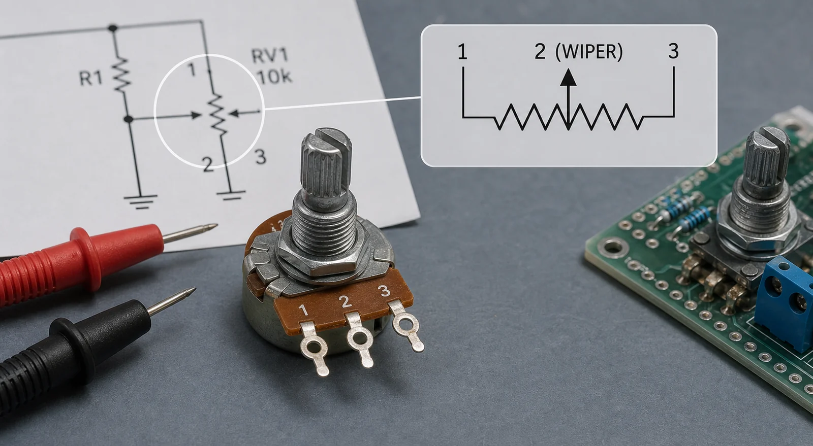
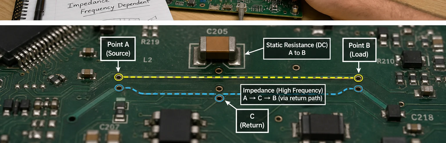
Resistance remains the correct first tool for many practical PCB tasks. If you are screening a power rail for a dead short before first power-up, checking whether a fuse element is open, comparing winding symmetry, verifying a current-shunt value, or estimating copper loss in a high-current path, resistance is the right language. It is also the right starting point when you suspect a damaged connector, lifted pad, cracked trace, or poor solder joint creating excess heat.
Even here, context matters. A four-wire measurement may be necessary when the target value is low enough that lead resistance distorts the result. A resistor that reads correctly at room temperature can still drift under load if thermal relief is poor or the package is undersized. A low-ohm motor path may measure “normal” statically but still fail dynamically because the driver sees a much harder inductive load during startup. Resistance answers one slice of the problem, not the whole behavior.
Where impedance becomes the real engineering problem
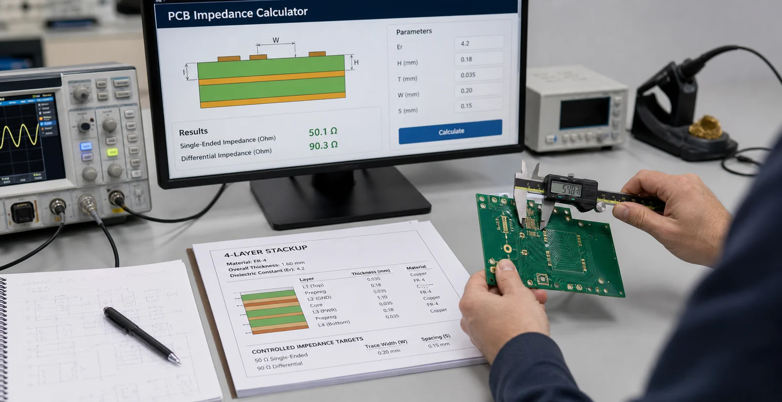
Impedance becomes the primary concern as soon as the signal changes fast enough, travels far enough, or stores enough magnetic or electric energy that phase and frequency response matter. In PCB design, that includes controlled-impedance traces, differential pairs, decoupling networks, switching regulators, transformer and inductor behavior, crystal networks, RF matching, sensor excitation, and cable interfaces.
A common failure pattern is to debug a switching node with a DC mindset. The ohmmeter says the plane is continuous and the resistor divider is correct, yet the regulator still oscillates. The real issue may be capacitor impedance at the switching frequency, excessive loop inductance, or a ground return path that forces current through a noisy geometry. Another pattern appears on digital interfaces. The trace resistance is negligible, but the line still overshoots because the impedance along the route and return reference is not controlled well enough for the edge rate.
That is also why board stackup and package choice influence results long after the schematic looks finished. A capacitor’s impedance minimum depends on value, ESR, ESL, and mounting. A connector transition can interrupt the return path and create an impedance discontinuity. A probe lead can add enough inductance to distort what you think you are measuring. Once the frequency content rises, physical implementation stops being a footnote.
How the distinction affects component selection
Choosing parts by resistance alone can produce avoidable field failures. A capacitor selected only by capacitance and voltage may still be wrong if its impedance curve is too high at the noise band you are trying to suppress. A ferrite bead chosen from a headline impedance number may disappoint if its DC resistance, current bias behavior, and actual noise spectrum are ignored. A shunt resistor may meet nominal ohms but create thermal drift or Kelvin-routing problems that corrupt measurement accuracy.
The same logic applies to repair. Replacing a damaged component with an “equivalent resistance” substitute can still fail when package parasitics, inductive behavior, or ESR profile differ enough to move a control loop or filter response. Engineers working on power modules, motor drivers, and mixed-signal boards see this often: the replacement part looks electrically close on paper but changes impedance in the region where the circuit is sensitive.
Measurement traps that hide an impedance problem
The most common trap is using a multimeter where an oscilloscope, LCR meter, impedance analyzer, or VNA-style measurement is needed. A DMM can confirm continuity or DC resistance, but it cannot tell you the frequency-dependent impedance that shapes ringing, resonance, or filter behavior. Another trap is measuring a component out of circuit and assuming the in-circuit impedance will match. Pads, vias, copper shape, neighboring components, and enclosure wiring all alter the result.
Probe technique also matters. Long ground leads on an oscilloscope can invent ringing that looks like a board defect. Measuring decoupling at a point far from the IC pins can hide the local impedance seen by the silicon. In service work, corrosion or flux residue may add leakage paths that barely change a high-level continuity check but shift impedance enough to upset analog sensing or high-impedance nodes.
If the symptom changes with frequency, load step, PWM duty, cable length, or probe placement, stop asking for a resistance-only answer. That behavior is usually telling you to switch models.
PCB examples where the distinction changes the design decision
Consider four common board-level cases:
- USB or high-speed digital routing: the copper resistance is rarely the limiting factor. Controlled impedance, reference continuity, and connector transition quality decide eye margin and reflections.
- Buck regulator input decoupling: a capacitor bank can have enough nominal capacitance but still the wrong impedance profile because ESL and mounting loop length are too high.
- Sensor front-end design: a source with nontrivial output impedance interacting with input capacitance can slow settling, distort readings, or change filter corners.
- Motor or relay driver outputs: winding resistance matters for current and heating, but transient impedance determines flyback stress, edge behavior, and EMI containment.
These examples are why broader PCB schematic design and implementation reviews have to stay linked. The schematic may express the intended function, but only an impedance-aware layout and measurement approach shows whether the circuit will behave the same way on the bench and in production. When the route, return, or load transition is wrong, the result often shows up later as impedance mismatch symptoms rather than an obvious DC fault.
A practical checklist for impedance versus resistance decisions
Use this sequence when deciding which model matters more in a real task:
- Ask whether the circuit behavior of interest is static/DC or changing with time, frequency, or edge rate.
- If the concern is heat, voltage drop, conductor loss, or a simple short/open check, start with resistance.
- If the concern is ringing, filtering, matching, loop stability, surge shape, or timing distortion, shift immediately to impedance.
- Check whether the package, mounting geometry, cable, or return path changes the result more than the nominal component value does.
- Choose the measurement method that matches the model: ohmmeter for resistance, but scope, LCR, impedance analyzer, or network-style methods for impedance behavior.
This approach prevents a common documentation mistake as well. When a design note says “low resistance path” but the actual requirement is controlled low impedance over a frequency band, the manufacturing and test teams can optimize the wrong feature. That shows up later as passing continuity, passing ICT, and failing real operation.
Conclusion
Resistance is the part of electrical opposition that burns power and causes static voltage drop. Impedance is the full behavior a circuit presents once capacitance, inductance, phase shift, and frequency enter the picture. On real PCBs, the difference is not academic. It decides whether a decoupling network works, whether a trace carries a fast edge cleanly, whether a filter lands in the right band, and whether a bench measurement is telling the truth. If your circuit changes character when the signal starts moving, stop treating impedance and resistance as the same thing.
FAQ
Is impedance the same as resistance in a DC circuit?
For a DC-only case with no reactive effect in play, impedance reduces to resistance because reactance is effectively zero. That equivalence breaks as soon as frequency-dependent behavior matters.
Why can a circuit pass a resistance check and still fail in operation?
A resistance check only confirms the static conductive path. Real operation may depend on impedance, which changes with frequency, edge rate, capacitance, inductance, mounting parasitics, and return-path geometry.
When should a PCB engineer care more about impedance than resistance?
Impedance matters more for high-speed routing, switching power loops, decoupling networks, sensor interfaces, transformers, cables, RF sections, and any circuit where timing, phase shift, or resonance affects performance.
Can component package choice change impedance even if the nominal value stays the same?
Yes. Package size, lead shape, pad geometry, via path, ESR, and ESL all change the effective impedance seen by the circuit, especially at higher frequencies or fast edge rates.