When someone searches for the schematic symbol for potentiometer, they usually are not trying to memorize another textbook drawing. They are trying to answer a practical question inside a real circuit: Which pin is the wiper, is this part being used as a divider or a variable resistor, and what does that mean for wiring, troubleshooting, or replacement?
That is why this topic deserves more than a one-line symbol label. The potentiometer symbol carries information about function, not just identity. If you read it correctly, you can tell whether the circuit expects an adjustable reference voltage, a gain control, a calibration trim, or a current-limiting element behaving like a rheostat.

What the potentiometer symbol is actually telling you
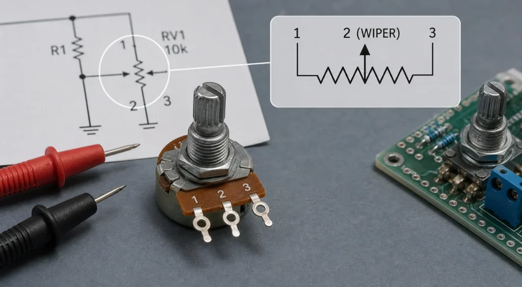
A potentiometer is fundamentally a three-terminal resistive element with a movable contact called the wiper. In a schematic, the fixed resistive path is shown like a resistor element, and the adjustable contact is shown with an arrow or moving-contact indicator touching the resistive path.
That single arrow is the most important feature of the symbol. It tells you the circuit has an adjustable node that can move along the resistance element. The output is not fixed at one end of the resistor. It is sampled or injected through the wiper.
If you already understand that, you can read most potentiometer circuits much faster than someone who only knows the part name.
How to identify the terminals correctly
Two end terminals
The ends of the resistive track connect to the two outer terminals. In many circuits those ends go to supply and ground, or to the high and low sides of the signal or reference path.
One wiper terminal
The arrow or sliding contact points to the adjustable terminal. That is the wiper. On the physical part, it is often the center pin on common panel potentiometers, though that is not a safe assumption for every footprint or trimmer style. Always confirm with the datasheet or footprint mapping.
Why this matters in repair
If the wiper is wired incorrectly, the circuit may still appear to change value but behave backward, lose full adjustment range, or inject noise at the wrong node. This is especially common when a technician replaces a panel pot with a mechanically similar part without rechecking the pin order.
Potentiometer vs rheostat symbol
This is one of the most valuable distinctions for readers.
A potentiometer normally uses all three terminals and acts as a voltage divider. A rheostat uses only two effective terminals and behaves as a variable resistor. On many schematics, the symbols look related because both involve an adjustable resistive path. The important difference is how many terminals are actually functionally used in the circuit.
If the wiper feeds an output node between two end terminals, you are likely looking at a potentiometer function. If one end and the wiper alone are used to control current or resistance in series with a load, the circuit is using the part more like a rheostat.
That distinction affects troubleshooting. A noisy divider output, unstable ADC reading, or scratchy audio control points to wiper behavior in a three-terminal use case. A variable current or brightness problem in a two-terminal path points to rheostat-like use.
Common symbol variants you may see
Different EDA libraries and drafting traditions draw the symbol a little differently.
Variable resistor style based on zigzag resistor symbols
In some diagrams the resistive path looks like a zigzag resistor with an arrow touching it. This is common in ANSI-style or older educational diagrams.
Rectangle resistor style with wiper arrow
Other diagrams use a rectangular resistor body with an arrow indicating the movable contact. This is often seen in IEC-style or CAD-library-driven schematics.
Trim potentiometer or preset notation
A trimmer or preset may use a related symbol but appear smaller, be labeled as VR, TRIM, or RV, or be placed in calibration-related parts of the circuit. The symbol still communicates adjustability, but the expected usage may be one-time setup instead of regular user adjustment.
How to read the symbol in real circuits
Voltage-divider use
This is the most common interpretation. One end goes high, one end goes low, and the wiper creates an adjustable output voltage. In analog front ends, reference setting circuits, and user-control inputs, this is often exactly what the symbol means.
Gain or sensitivity adjustment
In amplifiers, sensor interfaces, and comparator circuits, the potentiometer may not be there for a human-facing knob at all. It may be part of threshold or gain tuning. The schematic symbol tells you the circuit designer wanted an adjustable operating point.
User interface control
Volume knobs, brightness controls, menu-navigation knobs, and analog setpoint controls often use a potentiometer symbol that eventually connects into a PCB header or board-mounted part. In these cases, the symbol should be read together with the mechanical location and connector mapping, not only as an abstract resistor.
If you are tracing the signal path, ReversePCB’s guide on how to read electrical schematics is a useful companion, because the potentiometer symbol becomes much clearer once you identify where the adjustable node sits in the wider circuit.
Common mistakes engineers and technicians make
Confusing the wiper arrow with current direction
The arrow on a potentiometer symbol usually marks the movable contact, not the direction that current always flows. That misunderstanding leads people to misread the part’s function entirely.
Treating every adjustable resistor symbol as a potentiometer divider
Some circuits use the symbol in a two-terminal variable-resistance role. If you assume voltage-divider behavior without checking the actual connections, you can diagnose the circuit incorrectly.
Assuming the physical center pin is always the wiper without checking
That is common on many parts, but it is not guaranteed enough for blind field replacement. Board footprints, specialty packages, and vendor variations can still cause wiring mistakes.
Ignoring taper and application context
The symbol does not tell you whether the part is linear or logarithmic, audio taper or linear taper, panel pot or trimmer. That information must come from the BOM, mechanical drawing, or part number.
Better documentation habits for adjustable resistive parts
If you create schematics, make the role of the part obvious. Label whether the part is a user control, trim adjustment, bias setpoint, threshold control, or calibration element. If the wiper node is important to test, name that net clearly.
It also helps to keep the symbol and footprint mapping consistent with the real pin numbering. That reduces manufacturing mistakes and makes repair documentation far more reliable.
Final takeaway
The potentiometer schematic symbol is more than a resistor with an arrow. It tells you that the circuit includes an adjustable contact, and that contact usually defines the real behavior you care about. Read the wiper first, then the end terminals, and then decide whether the part is functioning as a true potentiometer divider or a rheostat-style variable resistor.
Once you build that habit, the symbol stops being a memorization task and becomes a quick way to understand adjustment, calibration, and user-control behavior in the circuit.
What does the arrow mean on a potentiometer symbol?
The arrow marks the wiper, which is the adjustable contact that moves along the resistive element. It usually does not indicate the permanent direction of current flow.
How is a potentiometer different from a rheostat on a schematic?
A potentiometer usually uses three terminals as a voltage divider, while a rheostat uses the wiper and one end terminal to act as a variable resistor.
Is the center pin always the wiper on a real potentiometer?
Often yes on common panel potentiometers, but not reliably enough to skip checking the datasheet or footprint. Replacement mistakes still happen when pin order is assumed.
Does the potentiometer symbol tell me whether the part is linear or audio taper?
No. The symbol shows adjustability and terminal function, but taper and exact electrical characteristics must come from the part number, BOM, or datasheet.