The phrase positive on a barrel jack schematic usually comes from a power-up check, a repair question, or a design review where nobody wants to guess wrong. That is the correct attitude. Barrel jacks look simple, but polarity confusion can damage regulators, reverse-protection parts, and downstream electronics very quickly.
On schematics, the most important point is that the symbol is trying to tell you which conductor is tied to the center pin and which is tied to the outer sleeve. In many products the common arrangement is center positive, but that is not a rule you should assume blindly. The drawing, the adapter marking, and the board input protection should all agree before power is applied.

What the polarity symbol is actually telling you
A barrel jack polarity mark is not just a cosmetic icon copied from an adapter label. It is a shorthand for an electrical mapping. One side of the symbol points to the center contact, and the other points to the cylindrical sleeve. The plus and minus signs show which conductor is assigned to each part of the connector.
When the symbol indicates center positive, the inner pin carries the positive supply and the sleeve is the return or negative path. When it indicates center negative, the relationship is reversed. That seems simple, but confusion happens when people remember the usual consumer pattern and stop reading the actual symbol in front of them.
Why this matters on a schematic and not only on the adapter
The schematic is where the connector assignment becomes part of the actual product design. Once the jack enters the circuit, the chosen polarity affects reverse-protection diodes, ideal-diode controllers, fuse placement, TVS orientation, and the labeling that assembly or service technicians will rely on later.
This is also where reading habits matter. If you already use a structured method like ReversePCB’s guide on how to read electrical schematics, the jack symbol should be treated as the start of the power path. Follow it from the connector to the protection stage, then to the regulator or load domains. That tells you not only what the polarity is supposed to be, but also how the designer intended to survive mistakes.
How center-positive is usually represented
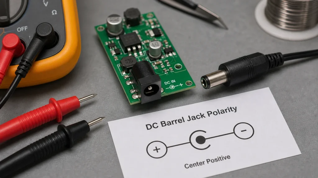
Most center-positive symbols show the plus sign tied to the center conductor and the minus sign tied to the outer ring. On printed labels, this often appears as a small diagram with a dot representing the center pin and a C-shaped ring representing the sleeve. In a schematic, the same idea may appear as a connector symbol, a note, or a nearby polarity graphic.
The important detail is that different libraries and documentation styles may draw the geometry differently while preserving the same meaning. Do not memorize only one exact artwork. Instead, identify which node is the center contact and which node is the sleeve.
Common places polarity confusion begins
One source of confusion is assuming that cable color tells the whole story. Another is reading a board silkscreen without confirming the adapter side. A third is seeing a generic DC input symbol and assuming the drafting team used the same polarity convention you use in your own documentation. None of those shortcuts are as reliable as tracing the intended node connections directly.
There is also a naming problem. Terms like positive barrel jack, DC jack polarity, and center positive adapter are often used interchangeably in casual conversation. On the bench, you need something less casual: which metal contact goes to which net, and how does the board react if the wrong adapter is connected?
What protection should appear after the jack
A well-designed input stage often follows the barrel jack with some form of protection. That may be a series diode, a MOSFET-based reverse-polarity stage, a fuse, a TVS diode, or a combination of these. The exact choice depends on efficiency, current level, cost, and failure policy.
If the board has no meaningful reverse-protection stage, a simple polarity mistake can damage the product immediately. If it does have protection, the schematic should make that visible. This is one reason broader power-rail naming literacy matters. ReversePCB’s explanation of VCC, VDD, VEE, VSS, and GND is helpful when the connector symbol is feeding multiple rails and the naming is not as obvious as a plain plus-minus pair.
How to check an unknown board safely
If you are repairing or reverse engineering a board with an existing barrel jack, start with the schematic if you have it. If not, inspect the board around the connector. Look for a diode orientation, a fuse, a regulator input, or silkscreen markings that reveal the intended polarity. Continuity checks between the sleeve and ground can often provide a fast hint, but they are still a hint, not a substitute for understanding the circuit.
If an adapter is already involved, inspect the adapter label too. The dangerous mistake is assuming the board and adapter match because both are common consumer parts. Many do, but the cost of being wrong is high enough that the assumption is not defensible.
Design mistakes that show up later in service
A product may work fine in the lab and still become troublesome in the field if the connector labeling is poor. Service technicians may grab a physically compatible adapter with the opposite polarity. Users may not notice a tiny printed symbol on the enclosure. If the circuit depends on correct polarity but gives no mechanical or electrical forgiveness, support failures become predictable.
For that reason, a good design does more than choose center positive or center negative. It also documents the choice clearly, protects against error where possible, and keeps the input path understandable to the next person who has to test or repair the board.
Final takeaway
“Positive on a barrel jack schematic” is really a question about whether the center pin or the sleeve is carrying the positive supply. The answer has to come from the actual symbol and the connected circuit, not from habit or guesswork.
Read the symbol, trace the power path, and verify the protection stage before applying power. That discipline takes seconds on paper and can save an entire board on the bench.
Does a barrel jack usually mean center positive?
Often yes, but not always. Many products use center-positive adapters, yet the only safe answer for a specific board comes from the symbol, labeling, and circuit around the connector.
What does the barrel jack polarity symbol describe?
It shows which supply polarity is tied to the center pin and which is tied to the outer sleeve, so the connector can be matched correctly to the power source.
Can the board survive a wrong-polarity adapter if the symbol is misread?
Only if the design includes suitable reverse-polarity protection. Without that protection, a polarity mistake can damage the input stage very quickly.
What is the fastest safe check on an unknown board?
Trace the connector into the power path, inspect the protection components, and compare the board markings with the adapter label before energizing the circuit.