If you’ve ever listened to an uncle playing blues guitar or a friend strumming a cheap plastic ukulele, you probably know what harmonic distortion is. It sounds like a very slight buzz, hiss, or whiz in the background of their performance. That is because these instruments aren’t able to produce their notes without some kind of distortion. This is also known as “nonlinearity” in engineering terms.
In this article, we explore what harmonic distortion is, why it occurs and how to prevent it from happening in your own home studio setup. Let’s get started!
What is Harmonic Distortion?
Harmonic distortion, also known as “involuntary feedback”, refers to the addition of new frequencies to a sound. This can happen when a signal is fed back into the system through which it was being played. This new signal can be heard as a buzzing or whistling sound. Harmonic distortion is most commonly seen in musical instruments and audio equipment. Musical instruments can’t produce their notes without the input of harmonic distortion. Audio equipment, however, needs to be designed to prevent harmonic distortion.
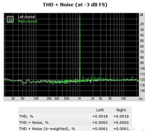
total harmonic distortion (THD)
Total Harmonic Distortion (THD) refers to the extra harmonic components of the output signal than the input signal caused by nonlinear components when the audio signal source passes through the power amplifier. Harmonic distortion is caused by the fact that the system is not completely linear, and we express it as a percentage of the root mean square of the newly added total harmonic component to the rms value of the original signal. For example, an amplifier that outputs 10V at 250Hz and 1V at 500Hz will have 10% second harmonic distortion. The sum of all additional harmonic levels is called total harmonic distortion. Generally speaking, the total harmonic distortion at the frequency of 500Hz is the smallest, so many products use the distortion of this frequency as its index.
The formula for calculating total harmonic distortion is as follows:
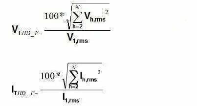
For voltage harmonics, TDH (%) is the total harmonic distortion, Vh is the power of each harmonic, and V1 is the total RMS output voltage (including fundamental and harmonic terms).
For current harmonics, TDH (%) is the total harmonic distortion, Ih is the current of each n harmonic, and I1 is the total RMS output current (including fundamental and harmonic terms).
How Does Harmonic Distortion Occur?
At the most basic level, harmonic distortion occurs when an input sound is too loud and is “fed back” into a system through an amplifier. This can happen in a home recording studio setup, when an instrument that’s plugged into the PA system starts to feed back. The easiest way to understand what happens is to think of two waves crashing against each other. One wave is your original audio signal, the other is the amplified sound that’s been fed back into the system through the speakers. These two waves combine to form something new. The original audio signal is still there, but so are the new frequencies that have been added by the feedback.
Measure Method
It can be known from the calculation formula of total harmonic distortion that the value of total harmonic distortion is closely related to the upper limit value H of the harmonic order. General harmonic measurement equipment such as harmonic analyzers are mostly suitable for power grid harmonic measurement, and the upper limit is usually within the 40th order.
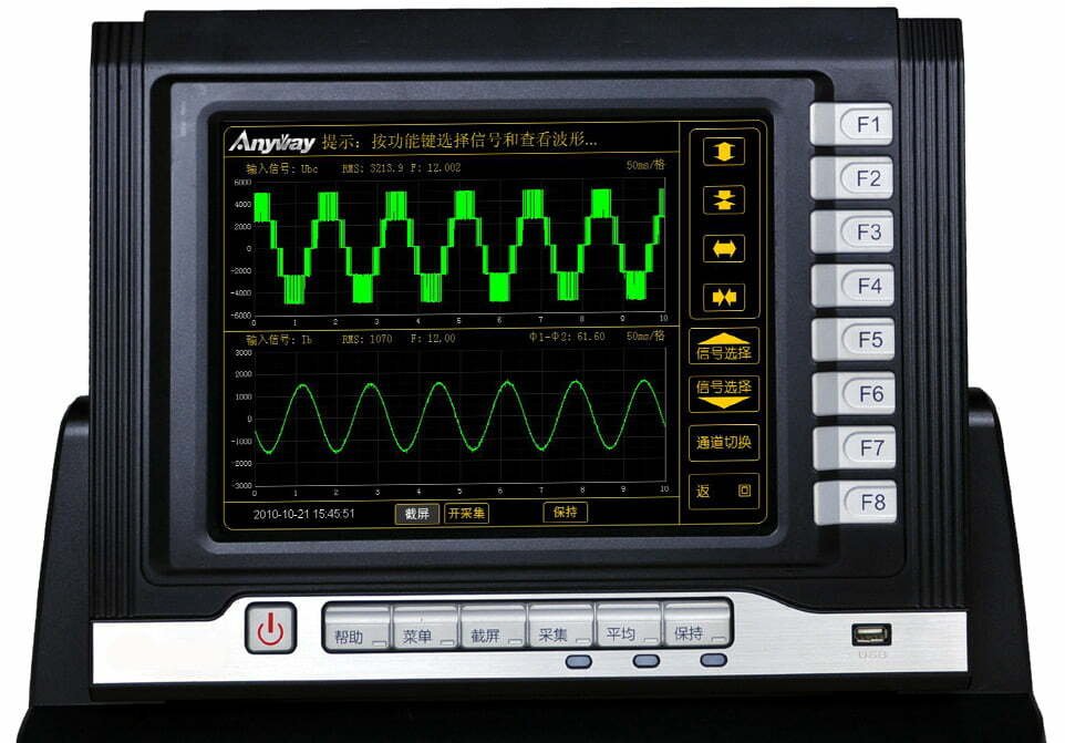
For harmonic emission equipment containing higher harmonics such as frequency converters, measuring total harmonic distortion requires special harmonic equipment that can measure higher harmonics, such as variable frequency power analyzers or broadband power analyzers. In addition, for high-voltage, high-current systems, it is also necessary to pay attention to the necessary bandwidth of the sensors used, such as variable frequency power sensors.
The Effect of Harmonic Distortion on PCB
Harmonic distortion is an important factor to consider when designing PCBs. It can cause problems with signal integrity and can lead to component damage. There are a few ways to mitigate harmonic distortion, including:
– Using low impedance power and ground planes
– Adding bypass capacitors to critical components
– Adding inductors to filter out high frequency noise
– Reducing the length of signal traces
Each of these methods has its own trade-offs and benefits, so it’s important to choose the right solution for your particular PCB design.
Preventing Harmonic Distortion
Harmonic distortion is one of the main problems that can occur when designing and manufacturing PCBs. It can cause a number of problems, including signal integrity issues, crosstalk, and electromagnetic interference (EMI).
There are a number of ways to reduce or eliminate harmonic distortion. One is to use differential signaling, which can cancel out many of the harmonics. Another is to use power supplies with low output impedance, which can also help to reduce harmonics.
Differential signaling is a technique that is often used in high-speed digital systems to reduce the effects of noise and crosstalk. In differential signaling, two signals are sent on separate wires, with one signal being the inverse of the other. The receiving device then combines the two signals, and any common-mode noise is cancelled out.
Power supplies with low output impedance can also help to reduce harmonics. A low-impedance power supply will have less of a voltage drop when current is drawn from it, meaning that the voltage at the load will be more stable. This can help to reduce or eliminate many of the problems caused by harmonic distortion.


